SITE MONITORING AND SERVICES AC8 USER MANUAL
TABLE OF CONTENTS 1.0 INTRODUCTION 1.1 1.2 1.3 1.4 1.5 1.6 1.7 1.8 1.9 Methods of Viewing and Configuring the AC8 . . . . . . . . . . . . . . . . . . . . . . . . . . . . . . . . . . . . . Data Logs . . . . . . . . . . . . . . . . . . . . . . . . . . . . . . . . . . . . . . . . . . . . . . . . . . . . . . . . . . . . . . . . . . Transformer Module. . . . . . . . . . . . . . . . . . . . . . . . . . . . . . . . . . . . . . . . . . . . . . . . . . . . . . . . . . Available Alarms . . . . . . . . . . . . . .
5.0 VIEW STATUS OPTIONS 5.1 View Active Alarms . . . . . . . . . . . . . . . . . . . . . . . . . . . . . . . . . . . . . . . . . . . . . . . . . . . . . . . . . 22 5.2 View Alarm Log . . . . . . . . . . . . . . . . . . . . . . . . . . . . . . . . . . . . . . . . . . . . . . . . . . . . . . . . . . . . 23 5.1.1 5.2.1 5.2.2 5.3 Event Log . . . . . . . . . . . . . . . . . . . . . . . . . . . . . . . . . . . . . . . . . . . . . . . . . . . . . . . . . . . . . . . . . .
7.6 Setup System - Setup Zones . . . . . . . . . . . . . . . . . . . . . . . . . . . . . . . . . . . . . . . . . . . . . . . . . . 46 7.6.1 7.7 Setup System - Setup Outputs . . . . . . . . . . . . . . . . . . . . . . . . . . . . . . . . . . . . . . . . . . . . . . . . 47 7.7.1 7.7.2 7.7.3 7.7.4 7.7.5 7.8 Modem Setup - Initialization String . . . . . . . . . . . . . . . . . . . . . . . . . . . . . . . . . . . . . . . . . . . . . Modem Setup - Additional Features (Service Terminal Interface only) . . . .
APPENDIX A - SERVICE TERMINAL INTERFACE . . . . . . . . . . . . . . . . . . . . . . . . . . . . . . . . . . . . . . . 79 A.1 A.2 Comparison of Functions: LCD and Service Terminal Interface. . . . . . . . . . . . . . . . . . . . . . 79 Connecting to the Service Terminal Interface . . . . . . . . . . . . . . . . . . . . . . . . . . . . . . . . . . . . 80 A.2.1 A.2.2 A.2.3 A.2.4 A.2.5 A.3 View Active Alarms . . . . . . . . . . . . . . . . . . . . . . . . . . . . . . . . . . . . . . . . . . . . . . . . . . .
FIGURES Figure 1 Figure 2 Figure 3 Figure 4 Figure 5 Figure 6 Figure 7 Figure 8 Figure 9 Figure 10 Figure 11 Figure 12 AC8 enclosure—external features . . . . . . . . . . . . . . . . . . . . . . . . . . . . . . . . . . . . . . . . . . . . . . . . . . . 2 AC8 enclosure—internal features . . . . . . . . . . . . . . . . . . . . . . . . . . . . . . . . . . . . . . . . . . . . . . . . . . . 2 Typical Configuration . . . . . . . . . . . . . . . . . . . . . . . . . . . . . . . . . . . . . . . . . . . . . . . . .
vi
Introduction 1.0 INTRODUCTION The Liebert AC8 is ideal for coordinated control of systems with redundant equipment, such as multiple environmental units or pumps. When the AC8 controller detects an alarm in an operating device, the AC8 enables a standby device and controls the device in alarm as configured, either leaving that device operating or disabling it. The AC8 controller can also balance usage of devices by rotating units through Operating and Standby modes according to a user-defined schedule.
Introduction 1.5 Outside Enclosure Overview The AC8’s controller board comes in an enclosure that is 2-3/4" deep and has a built-in liquid crystal display (LCD) and a key lock, as shown in Figure 1. The enclosure is made of metal to accommodate secure conduit fittings and protect components against environmental debris. Figure 1 AC8 enclosure—external features LCD for configuration and operation The enclosure has knockouts and access slots on top and bottom for cables and wires.
Introduction 1.6 Typical Configuration Figure 3 shows an example of external devices connected to the AC8’s controller board. Up to eight devices may be connected to the eight digital inputs and eight digital outputs. There may be up to four analog sensors connected to the analog inputs, and up to two devices connected to the control relay outputs. The EPOP connection allows for one device, possibly a UPS or generator input actuated during a power failure.
Introduction 1.7 Controller Board Overview The AC8’s controller board has connectors for eight digital inputs, four analog inputs, eight digital outputs, two control relay outputs and an EPOP contact input, as shown below. The board comes complete with light emitting diodes (LEDs) to display the status of connected devices, a battery pack for short-term backup, communications ports, power connections and other features necessary to control your operation.
Introduction Table 1 Controller board components (continued) Item Description For more information, see: J - Digital output connectors Each of the eight output connections is a two-state point: ON/OFF (energized/de-energized). An example of a field digital output point is an air unit On/Off control circuit. 3.0: 3.2.2: 5.6: 7.7: Wiring and Connections Connecting Digital Outputs View Output Status Setup System - Setup Outputs K - Status LEDs Indicates the operational status of the controller board.
Introduction 1.8 LED Indicators The AC8’s controller board has LED indicators that show the status of inputs, outputs and the common alarm, as well as the modem, SiteScan Web and EPOP connections. TB5: COMMON ALARM RELAY OUTPUTS BOTTOM + DS50 START P11 ENABLE AUDIBLE TB3, TB4, TB5 OUTPUT RELAY RATINGS: 24V, 3A CLASS 2 ONLY.
Introduction 1.9 Typical Sequence Figure 4 shows a typical sequence of how the AC8 functions after detecting a change in a monitored device. Many responses depend on configuration settings. This example shows what happens when a digital input changes state—assuming the input is defined as alarmable—and when the condition returns to normal. Figure 4 Example of typical sequence RESPONSES TO AN ALARM UNIVERSAL MONITOR 05-SEP-02 14:04:13 V5.100.
Installation 2.0 INSTALLATION This section provides instructions for installing, mounting and connecting power to the AC8. 2.1 Installation Considerations The AC8 must be installed indoors and may be mounted on the surface of a wall or flush-mounted, depending on the user’s application, the location of equipment and sensors to be monitored and the type of wall the unit will be mounted on. The AC8 should be mounted where it can be easily accessed.
Installation 2.2 Surface-Mounting the AC8 NOTE Removing the conduit knockouts before mounting the AC8 on the wall will ease installation and prevent strain on the mounting hardware and wall. It is imperative to remove the knockouts if the unit is to be flush-mounted. After determining where to place the unit, check to ensure that you have all the hardware required to install the panel on the surface of a wall. Obtain the needed tools and material. Required tools • • • • 2.2.
Installation 2.3 Flush-Mounting the AC8 NOTE Removing the conduit knockouts before mounting the AC8 on the wall will ease installation and prevent strain on the mounting hardware and wall. It is imperative to remove the knockouts if the unit is to be flush-mounted. The rectangular access doors on the top and bottom of the AC8 must be reversed so they slide the opposite direction. Leaving the doors as shipped from the factory prevents them from being opened when the panel is flush mounted in a wall.
Installation 2.4 Connect Power to the AC8 The AC8 must be supplied with 115VAC or 230VAC; the power supplied must match the rating of the unit’s Transformer Module. For information, consult your local dealer, Liebert representative or the Liebert Worldwide Support Group. The AC8 must be installed on a branch circuit protected by a certified 15A overcurrent device. ! WARNING ! CAUTION Check that power is removed from wires prior to installation.
Installation 24 VAC Output Power Connections To connect to the 24VAC outputs: 1. Install electrical wiring from device requiring 24VAC power to the Transformer Module. 2. Use copper wire only; proper wiring to use for power is 18, 20 or 22 AWG copper wire. Strip wire 1/4". 3. There are two 24 VAC output connectors (TB1 and TB2). Terminate wires to the connector as shown in Figures 6 and 7. TB1 and TB2 are NOT polarity sensitive. 4. Secure the wires to the connector.
Wiring and Connections 3.0 WIRING AND CONNECTIONS CAUTION ! 3.1 Switch OFF electric power to the AC8 before installing any wiring to the unit or changing input or output connections. The Power On/Off switch is in the top left corner of the unit, just below the battery pack. Wiring Specifications Input and output connections to the AC8 may be made in any order—it is not necessary, for example, to make all input connections before making any output connections.
Wiring and Connections 3.2 Connecting Digital Inputs and Digital Outputs The digital inputs, digital outputs and control relay outputs are found on the right side of the AC8’s printed wiring assembly board.
Wiring and Connections Connecting Digital Outputs ON PF To connect a digital output: 8 4 7 3 To reduce the risk of fire or electric shock, do not interconnect the outputs of different Class 2 circuits.
Wiring and Connections 3.2.4 Connecting Control Relay Outputs TB4: To connect a control relay output: ! 3.2.5 (BOTTOM) ON OFF PFM8 NUMBERING KEYS Relay 1 at left (green); Relay 2 at right (black) NC C NO NC C NO 2 ON OFF PFM3 1. Turn OFF electrical power to the AC8. 2. If necessary, remove a conduit knockout to permit wire entry into the AC8 enclosure. 3. Bring the wire(s) into the AC8 enclosure through a conduit knockout or access slot. 4.
Wiring and Connections 3.3 Connecting Analog Inputs The analog input connector blocks are at the bottom center of the AC8 printed circuit board, as shown below right. The blocks are two-part assemblies to permit easier connections. To determine the proper wire size, see Table 4 - Wiring specifications. To connect an input: 1. Turn OFF electrical power to the AC8. 2. If necessary, remove a conduit knockout to permit wire entry into the AC8 enclosure. 3.
Wiring and Connections 3.4 Connecting Common Alarm Outputs The common alarm relay, found in the top right corner of the AC8, permits the user to connect auxiliary notification equipment, such as lights, horns and sirens, to the AC8. To determine the proper wire size, see Table 4 - Wiring specifications. There are two connectors for the common alarm output. However, the connectors are not individual relay outputs. The connectors should be treated as a double-pole, double-throw (DPDT) relay.
Overview of Menus 4.0 OVERVIEW OF MENUS There are two ways to access the AC8: the LCD on the front of the enclosure and the Service Terminal Interface, which is accessible through any computer using a communications program. Many viewing and configuration tasks can be performed through either interface, but some are available only through the Service Terminal Interface. • Step-by-step instructions for all functions appear in Sections 5.0 through 7.0.
Overview of Menus 4.1 Opening Screen Overview The AC8 displays the Opening Screen at startup, as shown in Figure 8. • If any alarms are active, the Current Alarm screen appears. (Pressing any key on the LCD keypad will silence the audible alarm.) • If any analog input sensors are connected, the LCD screen will alternately display the Opening Screen and a screen showing the analog value of each sensor. If no alarms are present, the Main Menu appears. 4.
View Status Options 5.0 VIEW STATUS OPTIONS NOTE For ease of understanding, this section uses the LCD interface to illustrate most instructions, except for features that are available only through the Service Terminal Interface. All Service Terminal Interface screens appear in Appendix A - Service Terminal Interface.
View Status Options 5.1 View Active Alarms Main Menu The Active Alarm screen displays all alarms that are occurring, up to a > VIEW STATUS SYSTEM AND CONTROL maximum of 22. ↑↓=NEXT ↵=SELECT A Current Alarm screen appears automatically whenever an alarm occurs—except during setup. This screen can display only the two most recent active alarms. To view any other active alarms, use the View View Status Menu Active Alarms feature.
View Status Options 5.2 View Alarm Log Main Menu The Alarm Log contains up to 99 records of alarms that have occurred. Records are added to this log as alarms occur. > VIEW STATUS SYSTEM AND CONTROL ↑↓=NEXT To view the Alarm Log: • From the Main Menu, use the arrows ↑↓ to choose View Status, then press Enter ↵. • From the View Status Menu, use the arrows ↑↓ to choose View Alarm Log, then press Enter ↵. 5.2.
View Status Options 5.3 View Event Log Main Menu In addition to alarms, the AC8 tracks other changes in the Event Log to assist users with verifying operational and troubleshooting problems. Events reflect changes in the status of an input that is defined as an event or the change of state of an output (i.e., manually forced ON or OFF). Other events may be informational, such as a user login or an unsuccessful page attempt.
View Status Options 5.4 View Trend Log Main Menu The AC8 takes readings of configured analog input sensors at regular intervals and stores them in four separate trend logs, one for each sensor. The time interval is 30 minutes. Each log contains up to 100 records. Follow these steps to select a sensor and view its trend log: 5.4.1 Select a Sensor To select a sensor: • From the Main Menu, use the arrows ↑↓ to choose View Status, then press Enter ↵.
View Status Options 5.5 View Input Status Main Menu The Input Status option allows you to view the current status of all inputs: the four analog sensor inputs and the eight digital inputs. > VIEW STATUS SYSTEM AND CONTROL To view the Input Status: ↑↓=NEXT • From the Main Menu, use the arrows ↑↓ to choose View Status, then press Enter ↵. • From the View Status Menu, use the arrows ↑↓ to choose View Input Status, then press Enter ↵. 5.5.
View Status Options 5.6 View Output Status Main Menu The Output Status option allows you to view the current status of all eight outputs. > VIEW STATUS SYSTEM AND CONTROL To view the Output Status: ↑↓=NEXT • From the Main Menu, use the arrows ↑↓ to choose View Status, then press Enter ↵. • From the View Status Menu, use the arrows ↑↓ to choose View Output Status, then press Enter ↵. 5.6.1 Output Status The Output Status screen displays the status of each digital output.
View Status Options 5.7 View Pager Numbers Main Menu The AC8 may be set up to dial pager numbers when an alarm is detected. Up to four pagers may be configured, as described in 7.8 Setup System - Setup Modem & Pagers. > VIEW STATUS SYSTEM AND CONTROL ↑↓=NEXT ↵=SELECT The View Pager Numbers option allows you to view the pager numbers and PINs for all configured pagers. Use the following steps to select a View Status Menu pager and view its information. 5.7.
View Status Options 5.8 View Operation Main Menu The Operation option allows you to view the current settings for Auto Sequencing, Standby Testing and Staging in each zone. > VIEW STATUS SYSTEM AND CONTROL Use the following steps to select a zone and view the status of these features. 5.8.1 ↵=SELECT Select a Zone View Status Menu To select a zone: VIEW VIEW VIEW VIEW VIEW VIEW VIEW > VIEW VIEW • From the Main Menu, use the arrows ↑↓ to choose View Status, then press Enter ↵.
View Status Options 5.9 View Control Status Main Menu The Control Status option allows you to view the current status of the two control relays. > VIEW STATUS SYSTEM AND CONTROL To view the Control Status: ↑↓=NEXT • From the Main Menu, use the arrows ↑↓ to choose View Status, then press Enter ↵. • From the View Status Menu, use the arrows ↑↓ to choose View Control Status, then press Enter ↵. 5.9.1 Control Status The Control Status screen displays the status of each relay.
Silence Alarm & Backup Log Files (Service Terminal Interface) 6.0 SILENCE ALARM & BACKUP LOG FILES (SERVICE TERMINAL INTERFACE) This section describes two features that are available in the Service Terminal Interface: • Silence Alarm • Backup Log Files 6.1 Silence Alarm (Service Terminal Interface) The Silence Alarm menu item allows you to silence the audible alarm and reset the Common Alarm Relay output if the common alarm is configured to reset with silence.
Silence Alarm & Backup Log Files (Service Terminal Interface) 6.2 Back Up Log Files (Service Terminal Interface only) The AC8 maintains three types of logs—alarm, event and trend—that may be backed up to a remote computer. This feature is available only through the Service Terminal Interface. To back up any of the alarm, event or trend logs: 1. Connect to the AC8 either from a remote computer or through the RS232 port (see A.2 - Connecting to the Service Terminal Interface). 2.
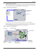
Silence Alarm & Backup Log Files (Service Terminal Interface) NOTE The following instructions refer to the Microsoft® Windows® HyperTerminal program. These steps may vary for other communications programs. 5. At the top of the HyperTerminal window, shown below, click on Transfer, then on Receive File. Enter folder Select Xmodem Enter filename for example, alarm.log 6.
System and Control Options 7.0 SYSTEM AND CONTROL OPTIONS NOTE For ease of understanding, this section uses the LCD interface to illustrate most instructions, except for features that are available only through the Service Terminal Interface. All Service Terminal Interface screens appear in Appendix A - Service Terminal Interface.
System and Control Options Figure 10 Menu overview - System and Control menu Opening Screen LIEBERT AC8 DD-MON-YY HR:MM:SS VX.XXX.
System and Control Options 7.2 Setup System - Overview The Setup System screen displays seven options that allow you to configure input and output devices and their relationships, the common alarm, the modem, pagers to be dialed when alarms occur, and a variety of system details, such as login password and system date and time: • • • • • • • • • 7.
System and Control Options 7.3.1 Change Label (Name of Input) Setup Inputs Menu Each input has a default label (Device_1, Device_2, etc.) that you may change to a more descriptive name for ease in recognizing alarms and events associated with the input. The label may consist of up to eight characters (see Table 14 for valid characters). The device name assigned through this menu is also displayed for the corresponding output.
System and Control Options 7.3.4 Set Up Alarmable Inputs in Latched or Unlatched Mode Alarmable input points may be set up in Latched mode (Y), which requires the user to clear the AC8 alarms after an alarm has occurred, or Unlatched mode (N), in which alarms will automatically clear after a return-to-normal state. The default setting for alarmable inputs is L (Latched). Any input defined as an event is automatically Unlatched.
System and Control Options 7.4 Setup System - Setup Common Alarm The audible alarm sounds after the AC8 detects an alarm condition in any input that has been defined as alarmable, including digital and analog sensor inputs. Once the alarm is silenced, there are two options: • By default, the common alarm remains energized until the input alarm is cleared. • You may change this setting to de-energize the common alarm automatically once the alarm is silenced.
System and Control Options 7.5 Setup System - Setup Sensor The AC8 has four analog sensor input points that may be configured individually. The panel monitors connected equipment for any 4-20 mA input—for example, temperature and humidity.
System and Control Options 7.5.1 Identify the Sensor as Connected Setup Sensor Menu To make use of an analog sensor, you must specify it as Connected (Y). By default, analog sensors are Not connected (N). Disconnecting a sensor will turn off staging for that sensor’s zone if staging has been turned on for the zone (see 7.10.6 - Specify Staging for details on staging). • From the Setup Sensor Menu, choose Connected, as shown at right, and press Enter ↵.
System and Control Options 7.5.4 Change 4 mA Value Setup Sensor Menu For the 4 mA value, enter the smallest value for the range of the sensor—for example, 50°F for a temperature sensor with a range of 50°F to 90°F. The default value for each sensor is +045.0. Values that can be entered range from -999.9 to +999.9. To enter a new value: • From the Setup Sensor Menu, choose 4 mA for the selected sensor and press Enter ↵. • To change the 4 mA value: • Use the arrows ↑↓ to choose a character.
System and Control Options 7.5.7 Define Sensor as Alarmable or Event Setup Sensor Menu Each sensor may be defined as Alarmable (AL) or as an Event (EV). • For a sensor defined as alarmable, the following alarm reactions occur when the high-setpoint threshold is crossed: the LCD flashes, the audible horn sounds, configured pager numbers will be notified and a record is entered in the Alarm Log. • For a sensor defined as an event, the high-setpoint occurrence is recorded in the Event Log.
System and Control Options 7.5.9 Change Low Setpoint Setup Sensor Menu When the sensor detects a condition below the Low Setpoint value, an alarm or event will occur, depending on the sensor configuration. The Low Setpoint value must not be set below the sensor’s 4 mA value plus the offset value. For example, if the 4 mA value is 50°F and the Offset value is 5°F, the Low Setpoint must be 55°F or higher. The default Low Setpoint for each sensor is +0050.0.
System and Control Options 7.5.11 Set Up Delay Time Setup Sensor Menu Each sensor may be set up with a specified time delay between the triggering of a high or low setpoint—a monitored sensor crosses the high or low setpoint threshold—and any response by the AC8. This feature can prevent transient conditions from prompting unnecessary responses.
System and Control Options 7.6 Setup System - Setup Zones The AC8 has four zones that may be used to define different areas—rooms or sections of a room. If set up with four zones, the AC8 effectively performs as four separate units, controlling each zone separately, for example, using a different rotation sequence for devices in each zone. A single zone may have one to eight outputs associated with it. The minimum number of outputs per zone is one, and the maximum for all zones combined is eight.
System and Control Options 7.7 Setup System - Setup Outputs The AC8 has eight outputs that may be configured individually. These outputs correspond to the eight numbered inputs. For example, Device_1 is the unit connected to Input 1 and to Output 1. The output name is the same as the input name, as described in 7.3.1 Change Label (Name of Input). To configure an output: Log In and Choose Setup System • From the Main Menu, use the arrows ↑↓ to choose System and Control, then press Enter ↵ (see 7.
System and Control Options 7.7.2 Define Operating or Standby Mode Setup Outputs Menu Each output may be defined as Operating (OP), Standby (ST), or Not Used (NU). This setting takes precedence over any setting in the override menu (see 7.12 - Override Output).
System and Control Options 7.8 Setup System - Setup Modem & Pagers To use the modem and pager features, be sure to connect the phone line connector to a telephone wall jack using an RJ11 cord, as described in 3.6.2 - Phone Line Connector. 7.8.1 Modem Setup - Initialization String The AC8 has an on-board modem that offers dial-up access to all LCD functions as well as features available only through the Service Terminal Interface (see A.1 - Comparison of Functions: LCD and Service Terminal Interface).
System and Control Options International Dialing 7. To enable international dialing involving countries that do not support country code B5 (see Table 22), you must add the appropriate country codes to the initialization string using the format: +GCI=xx where xx is the country code. (This also requires the modem model MT5600SMI; the model number can be found on the modem label.) Note: For countries that support B5, there is no need to add country codes to the init string.
System and Control Options 7.8.2 Modem Setup - Additional Features (Service Terminal Interface only) The Service Terminal Interface offers four additional options for the modem that are not available through the LCD interface: • • • • Enter AC8 phone number Enable modem diagnostic messages Change modem dial prefix Change modem hang up delay after a call To access these options: • Connect to the AC8 either from a remote computer or through the RS232 port (see A.
System and Control Options Enable Modem Diagnostic Messages Enabling modem diagnostics will provide the following additional information about the modem to the computer using the Service Terminal Interface: Hang-up modem Modem model number No dial tone No carrier Busy No answer Pager checksum error Pager pin number error Error (indicates incorrect phone number, dial prefix or modem initialization string) For alphanumeric pager failures: Paging company non answer on 1st Paging company non answer on 2nd Pagi
System and Control Options 7.8.3 Pager Setup - Pager Number and PIN The AC8 may be configured to dial numeric or alphanumeric pagers when an alarm is detected. You may enter up to four pager numbers—all configured pagers will be dialed each time an alarm occurs. For each configured pager, you must enter the pager number to be dialed and the pager’s Personal Identification Number (PIN). See 8.1 - AC8 Specifications for supported pager settings.
System and Control Options Enter a Pager Number • From the Setup Pager Menu, choose Setup Pager Number for the selected pager—Setup Pager 1 Number in the example at right—and press Enter ↵. • See Table 24 for guidelines on entering the pager number, which may consist of up to 40 characters. To enter the pager number: • Use the arrows ↑↓ to choose a character. • Press Enter ↵ to advance to the next character position. • When finished, press Enter ↵ again.
System and Control Options 7.8.4 Pager Setup - Communications Check (Service Terminal Interface only) The Service Terminal Interface offers two additional options for pager setup, which are not available through the LCD interface: • Enable communications check • Enter time to perform communications check To access these options: • Connect to the AC8 either from a remote computer or through the RS232 port (see A.2 - Connecting to the Service Terminal Interface).
System and Control Options Enable Communications Check Enabling this function permits a daily communications test between the AC8 and the selected pager. Once each day the AC8 dials the pager at a specified time and sends this message: “AC8 COMM CHECK.” (The time of the test is specified at the next prompt, Enter Time To Perform Communications Check.) • At the Enable Communications Check prompt, enter Y (Yes - enable) or N (No - disable).
System and Control Options 7.
System and Control Options 7.9.1 Change Password Setup System Info Menu A password is required to access the AC8’s system and control options, as described in 7.1 - Login. The password consists of four characters (see Table 14 for valid characters). The default password is AAAA. Change the Password To change the password: • From the Setup System Info Menu, use the arrows ↑↓ to choose Change Password, then press Enter ↵. • To change your password: • Use the arrows ↑↓ to choose a character.
System and Control Options 7.9.3 Setup Site ID Setup System Info Menu You may enter a Site ID to identify the AC8’s location, using a name that may consist of up to 40 characters (see Table 14 for valid characters). The Site ID will appear with each alarm. To enter or change the Site ID: • From the Setup System Info Menu, use the arrows ↑↓ to choose Setup Site ID, then press Enter ↵. • To enter a Site ID: • Use the arrows ↑↓ to choose a character.
System and Control Options 7.9.5 Backup and Upload Configuration File (Service Terminal Interface only) This operation may be performed only through the Service Terminal Interface. It permits the user to make a copy of the AC8’s configuration settings and save it as a file on the computer connected through the RS232 port. Should the need arise, the user can upload the configuration file from the computer to the AC8, instead of re-entering the settings manually. To access these options: 1.
System and Control Options Back Up the Configuration File 8. At the prompt to Initiate a Backup of Configuration File, enter Y (Yes - begin) or N (No - cancel). The current setting appears in brackets—[N] in the following example. >INITIATE A BACKUP OF CONFIGURATION FILE-YES(Y) OR NO(N)? >[N] >[ NOTE The following instructions refer to the Microsoft Windows HyperTerminal program. These steps may vary for other communications programs. 9.
System and Control Options Upload the Configuration File 13. At the prompt to Initiate an Upload of Configuration File, enter Y (Yes - begin) or N (No - cancel). The current setting appears in brackets—[N] in the following example. >INITIATE AN UPLOAD OF CONFIGURATION FILE-YES(Y) OR NO(N)? >[N] >[ NOTE The following instructions refer to the Microsoft Windows HyperTerminal program. These steps may vary for other communications programs. 14.
System and Control Options 7.9.6 Setup Serv Ph Num - Enter Phone Number The Service Phone Number (Serv Ph Num) is used for remote monitoring by Liebert Global Services. The number is designed to allow remote monitoring services to connect to the AC8. All alarms will be sent to this number. When an alarm occurs, this number is dialed before any of the four pager numbers.
System and Control Options 7.9.7 Setup Serv Ph Num - Communications Check (Service Terminal Interface only) The Service Terminal Interface offers two additional options for setting up the Service Phone Number (Serv Ph Num) that are not available through the LCD interface: • Enable communications check • Enter time to perform communications check To access these options: • Connect to the AC8 either from a remote computer or through the RS232 port (see A.2 - Connecting to the Service Terminal Interface).
System and Control Options 7.9.8 Factory Defaults Setup System Info Menu At any time, you may restore all default values for settings in the AC8 as it was shipped. NOTE This action will overwrite any configuration settings. You may want to back up your settings before restoring the factory defaults. See Backup and Upload Configuration File (Service Terminal Interface only) in A.6.7 - Setup System Info for details on backing up settings using the Service Terminal Interface.
System and Control Options NOTE The following instructions refer to the Microsoft Windows HyperTerminal program. These steps may vary for other communications programs. 2. The firmware update is a two-step process—this step describes how to upload the file prog###.s19 (where ### is a number—for example, prog118.s19) to the AC8: a. At the top of the HyperTerminal window, shown below, click on Transfer, then on Send File. Enter filename prog###.s19 or flash####.s19 Select Xmodem Send button b.
System and Control Options 7.9.10 Initiate Remote Alarm Test (Service Terminal Interface only) The service phone number is used for remote monitoring by Liebert Global Services. The Service Terminal Interface may be used to test communications between the AC8 and the service modem. This test will send a “DIAL OUT TEST PASSED” message to the service phone number.
System and Control Options 7.10 Setup Operation The AC8’s operation features allow you to set up a rotation sequence to Setup System Menu alternate which devices are operating and which are placed on SETUP INPUTS Standby, as well as test devices while in Standby mode and specify SETUP COMMON ALARM what to do when a Standby device goes into alarm as it is powered up.
System and Control Options 7.10.1 Turn Automatic Sequencing On or Off Use automatic sequencing to set up a schedule for rotation of redundant devices. For example, three devices might be in operating mode while a fourth device is in standby mode. Every two days, the AC8 returns the standby device to operating mode and places one of the operating devices on standby.
System and Control Options 7.10.2 Turn Standby Testing On or Off Standby testing permits scheduling an automatic operational check of devices in Standby mode. When this feature is activated (ON), the AC8 tests all devices in Standby mode by putting each device in operating mode for a designated time. If an operating unit is designated as disabled on alarm, the unit is turned off during standby testing, then turned on when the test ends.
System and Control Options 7.10.4 Specify Hold Delay Time After an output changes state, the hold delay timer directs the AC8 to ignore all inputs in the same zone for the specified time. This delay is the amount of time that must elapse before the AC8 acknowledges a change of state in any input. The default is 10 minutes (displayed as 10 MIN : 00 SEC).
System and Control Options 7.10.6 Specify Staging Staging allows a standby device to be turned On when a sensor detects a monitored point reaching a specified setpoint. The AC8 continues to turn On additional standby units, if available, at specified intervals. Staging also turns Off devices as the condition returns to normal. Devices are turned off in a last-on / first-off order, triggered by decreases of half the specified sensitivity increment.
System and Control Options 7.11 Setup System - Setup I/O Matrix The Setup I/O Matrix menu allows you to configure the AC8’s digital and analog inputs to trigger various actions in either or both of the two control relays. Each relay can be set up to respond to more than one digital or analog input. Almost any mapping combination can be used.
System and Control Options 7.11.2 Set Up Mapping for an Analog Sensor Input • Use the arrows ↑↓ to choose Map Sensor To Relay from the Map Input/Sensor Menu, and press Enter ↵. • From the Select Sensor Menu, choose the input you want—for example, Sensor_1 High Stpt—and press Enter ↵.
System and Control Options 7.12 Override Output The Override Output feature allows you to manually change the state of any digital output to ON or OFF, overriding automatic control by the AC8 (the default setting for all outputs). This menu also allows you to release the manual override, returning any output to automatic control. There are two ways to override automatic control of outputs: • Use the Override Output menu, as described in this section, to turn any output ON or OFF.
System and Control Options 7.13 Clear Alarms & Logs Main Menu The Clear Alarms & Logs menu allows you to clear active alarms or delete all records from any of the AC8’s three logs: alarm, event and trend logs. VIEW STATUS > SYSTEM AND CONTROL ↑↓=NEXT ↵=SELECT To clear alarms or logs: Login Log In and Choose Clear Alarms & Logs • From the Main Menu, use the arrows ↑↓ to choose System and Control, then press Enter ↵ (see 7.1 - Login for help). • Enter your password at the Login screen.
System and Control Options 7.13.3 Clear the Event Log The event log contains up to 99 records of events detected by the AC8. You may want to clear the log after backing up the file or simply to free up space. NOTE Before deleting the records in the event log, you may want to back up the file to a remote computer using the Service Terminal Interface, as described in 6.2 - Back Up Log Files (Service Terminal Interface only).
Specifications 8.0 SPECIFICATIONS 8.1 AC8 Specifications Transformer Module Power Requirements 115VAC UML11500 230VAC UML23000 115VAC ±10% of nominal; 60Hz, 4A, 460VA 230VAC ±10% of nominal; 50Hz, 0.5A, 115VA Dimensions W x D x H, in. (mm) 18 x 2-3/4 x 18 (457.2 x 69.85 x 457.2) Weight (Assembled) 20.56 lb. (9.
Comparison of Functions: LCD and Service Terminal Interface APPENDIX A - SERVICE TERMINAL INTERFACE The Service Terminal Interface allows access to all functions of the AC8, including some that are not possible through the LCD interface. This interface is accessible through any computer using a communications program such as Microsoft® Windows® HyperTerminal.
Connecting to the Service Terminal Interface A.2 CONNECTING TO THE SERVICE TERMINAL INTERFACE This section describes how to set up and connect to the Service Terminal Interface. A.2.1 Connection Methods There are two ways to access the Service Terminal Interface: • Direct—Use a null modem cable to connect a computer’s COM1 port to the AC8’s RS232 port, OR • Remote—Use a remote computer’s modem to dial the telephone number of the phone line connected to the AC8.
Connecting to the Service Terminal Interface 5. In the Connect To window, shown below, select the appropriate connection method from the Connect Using drop-down list: DIRECT CONNECTION REMOTE CONNECTION Choose COM1 & proceed to Step 6 Direct Connection via RS232 • To set up a direct connection via the AC8’s RS232 port, select COM1 as shown above. This opens the COM1 Properties window. • Proceed to Step 6 (next section).
Connecting to the Service Terminal Interface A.2.4 Set Up the Connection’s Properties The following steps are needed for both direct and remote connection to the AC8. Properties Setup 8. Open the Properties window by clicking on File, then on Properties, as shown below left. Settings tab 9.
Connecting to the Service Terminal Interface A.2.5 Connect to the Service Terminal Interface After creating and setting up a connection, use a communications program such as HyperTerminal to access the AC8’s Service Terminal Interface. 1. Verify communications connections between the remote computer and the AC8: a. For direct connection (via RS232 port): • Connect a null modem cable from the computer’s COM1 port to the AC8’s RS232 port (for location, see 3.6.1 - RS232 Connector). b.
Overview of Menus A.3 OVERVIEW OF MENUS The Main Menu offers choices for viewing the status of the AC8, silencing the audible alarm and backing up the unit’s log files. It also allows access to the System and Control features, which require a password. The following shows where to find examples of the Main Menu screens: Main Menu 1=VIEW ACTIVE ALARMS For sample screens, see: A.
View Status Menus A.4 VIEW STATUS MENUS The View Status menu allows any user to view currently active alarms, monitoring data stored in the alarm, event and trend logs, the status of all inputs and outputs, and the four pager numbers. Main Menu After connecting to the Service Terminal Interface, the Main Menu appears, as shown below. This section presents Service Terminal Interface screens for options 1 through 7: Main Menu LIEBERT AC8 VX.XXX.
View Status Menus A.4.2 View Alarm Log For details on this feature, see 5.2 - View Alarm Log. View Alarm Log ALARM LOG Alarm history SENSOR_2 80.0 DEG HIGH SETPOINT ALARM 29-AUG-05 09:29:10 MODEM INTERNAL FAULT 29-AUG-05 09:20:10 DEVICE_8 ALARM CONTACT CLOSED 29-AUG-05 09:19:10 SENSOR_2 79.
View Status Menus A.4.3 View Event Log For details on this feature, see 5.3 - View Event Log.
View Status Menus A.4.4 View Trend Log For details on this feature, see 5.4 - View Trend Log. View Trend Log TREND LOG Trend history for each sensor Select sensor for trend you want to view. 1=SENSOR_1 2=SENSOR_2 3=SENSOR_3 4=SENSOR_4 5=RETURN TO MAIN MENU SELECT A NUMBER:1 TREND LOG Trend history SENSOR_1 NORMAL 28-AUG-05 75.4 DEG 15:45:10 SENSOR_1 70.5 DEG LOW SETPOINT EVENT 28-AUG-05 15:15:10 SENSOR_1 79.
View Status Menus A.4.5 View Input Status For details on this feature, see 5.5 - View Input Status. View Input & Sensor Status INPUT & SENSOR STATUS Sensor values & discrete inputs status INPUT SENSOR_1 SENSOR_2 SENSOR_3 SENSOR_4 DEVICE_1 DEVICE_2 DEVICE_3 DEVICE_4 DEVICE_5 DEVICE_6 DEVICE_7 DEVICE_8 STATUS 80.0 -----80.0 79.
View Status Menus A.4.7 View Pager Numbers For details on this feature, see 5.7 - View Pager Numbers.
View Status Menus A.4.8 View Operation For details on this feature, see 5.8 - View Operation. View Operation OPERATION STATUS Autosequencing and Standby Testing 1=ZONE 1 2=ZONE 2 3=ZONE 3 4=ZONE 4 5=RETURN TO MAIN MENU SELECT A NUMBER:1 ZONE 1 AUTO SEQUENCING ON DAY 01 OF 02 (08:55) STANDBY TESTING ON DAY 00 OF 03 (00:00) STAGING ON CURRENT VALUE 73.8 DEG SET VALUE +0070.0 DEG SENSITIVITY +005.0 DEG 1=VIEW A DIFFERENT ZONE 2=RETURN TO MAIN MENU SELECT A NUMBER: A.4.
Silence Alarm & Back Up Log Files (Service Terminal Interface only) A.5 SILENCE ALARM & BACK UP LOG FILES (SERVICE TERMINAL INTERFACE ONLY) This section presents two options from the Main Menu that are available via the Service Terminal Interface only. Main Menu After connecting to the Service Terminal Interface, the Main Menu appears, as shown below. This section presents Service Terminal Interface screens for options 8 and 9: Main Menu LIEBERT AC8 VX.XXX.
Silence Alarm & Back Up Log Files (Service Terminal Interface only) A.5.2 Back Up Log Files (Service Terminal Interface only) For details on this feature, see 6.2 - Back Up Log Files (Service Terminal Interface only).
Silence Alarm & Back Up Log Files (Service Terminal Interface only) Back Up Trend Log Files Backup Log Files - Trend Log Files BACKUP LOG FILES Backup alarm, event and trend log files 1=BACKUP 2=BACKUP 3=BACKUP 4=BACKUP 5=BACKUP 6=BACKUP 7=RETURN ALARM LOG FILE EVENT LOG FILE TREND LOG FILE-SENSOR_1 TREND LOG FILE-SENSOR_2 TREND LOG FILE-SENSOR_3 TREND LOG FILE-SENSOR_4 TO MAIN MENU SELECT A NUMBER:3 >INITIATE A BACKUP OF TREND LOG-YES(Y) OR NO(N)? >[N] >[ INSTRUCTIONS TO PERFORM BACKUP: ASSUMES USING MI
Setup Menu A.6 SETUP MENU The Setup menu allows the user to configure the AC8—setting up inputs and outputs and an input/ output matrix to trigger actions, the modem and pagers, and system features such as date and time. This menu also provides a vehicle for manually changing the state of an output to ON or OFF, clearing active alarms and deleting records from the AC8’s alarm log, event log and trend logs.
Setup Menu Setup Menu This section presents Service Terminal Interface screens for each of the following: Setup Menu See: Description 1=SETUP INPUT Section A.6.1 Configure digital inputs 2=SETUP COMMON ALARM Section A.6.2 Set up the common alarm to reset with silence 3=SETUP SENSOR Section A.6.3 Configure analog inputs 4=SETUP ZONES Section A.6.4 Assign devices to separate areas 5=SETUP OUTPUTS Section A.6.5 Configure digital outputs 6=SETUP MODEM&PAGERS Section A.6.
Setup Menu A.6.1 Setup Inputs For details on this feature, see 7.3 - Setup System - Setup Inputs.
Setup Menu A.6.3 Setup Sensor For details on this feature, see 7.5 - Setup System - Setup Sensor. Setup Sensor SETUP SENSOR Setup for analog input points Select sensor to edit SENSOR VALUE 1=SENSOR_1 80.0 DEG 2=SENSOR_2 ------ DEG 3=SENSOR_3 80.0 DEG 4=SENSOR_4 79.5 RH 5=RETURN TO SETUP MENU 6=RETURN TO MAIN MENU SELECT A NUMBER:1 >IS THE SENSOR CONNECTED-YES(Y) OR NO(N)? >[N] >[] >CHANGE SENSOR LABEL(8 CHARACTERS MAX). >[SENSOR_1] >[] >CHANGE UNITS LABEL(3 CHARACTERS MAX).
Setup Menu A.6.4 Setup Zones For details on this feature, see 7.6 - Setup System - Setup Zones. Setup Zones SETUP ZONES Select zones and number of devices in the zone ZONES # DEVICES 1=ZONE 1 4 2=ZONE 2 0 3=ZONE 3 0 4=ZONE 4 0 5=RETURN TO SETUP MENU 6=RETURN TO MAIN MENU SELECT A NUMBER: ># DEVICES IN ZONE 1 >[4] >[ A.6.5 Setup Output For details on this feature, see 7.7 - Setup System - Setup Outputs.
Setup Menu A.6.6 Setup Modem & Pagers For details on this topic, see 7.8 - Setup System - Setup Modem & Pagers. Pager Setup For details on this feature, see 7.8.3 - Pager Setup - Pager Number and PIN and 7.8.4 - Pager Setup - Communications Check (Service Terminal Interface only).
Setup Menu Modem Setup For details on this feature, see 7.8.1 - Modem Setup - Initialization String and 7.8.2 - Modem Setup - Additional Features (Service Terminal Interface only). Setup Modem & Pagers - Modem Setup SETUP MODEM&PAGERS Input pager and modem information Select pager or modem CURRENT NUMBER ******************* An "A" is required as 1st character for an alpha pager, an "N" for a numeric pager, and an "M" for a remote modem.
Setup Menu A.6.7 Setup System Info This section presents Service Terminal Interface screens for choices 1 through 9 in the Setup System Information menu shown below. For details on this topic, see 7.9 - Setup System - Setup System Info.
Setup Menu Set Date & Time/Automatic Daylight Saving Time For details on this feature, see 7.9.2 - Change Date & Time/Automatic Daylight Saving Time. Set Date & Time SET DATE & TIME CURRENT DATE & TIME 28-AUG-05 14:45:10 1=SET DATE & TIME 2=RETURN TO SETUP SYSTEM INFO MENU 3=RETURN TO SETUP MENU 4=RETURN TO MAIN MENU SELECT A NUMBER:1 >SET DATE & TIME(DD-MON-YY HR:MM:SS).
Setup Menu Backup and Upload Configuration File (Service Terminal Interface only) For details on this feature, see 7.9.5 - Backup and Upload Configuration File (Service Terminal Interface only).
Setup Menu Setup Service Phone Number For details on this feature, see 7.9.6 - Setup Serv Ph Num - Enter Phone Number and 7.9.7 Setup Serv Ph Num - Communications Check (Service Terminal Interface only). Setup Service Phone Number SETUP SERVICE PHONE NUMBER This number receives all alarms in addition to the 4 pagers CURRENT NUMBER 1=SETUP SERVICE PHONE NUMBER 2=RETURN TO SETUP SYSTEM INFO MENU 3=RETURN TO SETUP MENU 4=RETURN TO MAIN MENU ****************** An “M” is required as 1st character.
Setup Menu Firmware Update (Service Terminal Interface only) For details on this feature, see 7.9.9 - Perform Firmware Update (Service Terminal Interface only).
Setup Menu A.6.8 Setup Operation For details on this feature, see 7.10 - Setup Operation. Auto Sequencing For details on this feature, see 7.10.1 - Turn Automatic Sequencing On or Off.
Setup Menu Standby Testing For details on this feature, see 7.10.2 - Turn Standby Testing On or Off.
Setup Menu Failed Standby For details on this feature, see 7.10.3 - Specify Failed Standby Response.
Setup Menu Hold Delay For details on this feature, see 7.10.4 - Specify Hold Delay Time.
Setup Menu Restart Delay For details on this feature, see 7.10.5 - Specify Restart Time.
Setup Menu Staging For details on this feature, see 7.10.6 - Specify Staging.
Setup Menu A.6.9 Override Output For details on this feature, see 7.12 - Override Output.
Setup Menu A.6.10 Clear Alarms & Logs For details on this topic, see 7.13 - Clear Alarms & Logs. Clear Active Alarms For details on this feature, see 7.13.1 - Clear Active Alarms.
Setup Menu Clear the Event Log For details on this feature, see 7.13.3 - Clear the Event Log. Clear Alarms & Logs - Clear the Event Log CLEAR ALARMS&LOGS Clear active alarms or log records Select the log to clear 1=CLEAR ACTIVE ALARMS 2=CLEAR ALARM LOG 3=CLEAR EVENT LOG 4=CLEAR TREND LOGS 5=RETURN TO SETUP MENU 6=RETURN TO MAIN MENU SELECT A NUMBER:3 >CLEAR ALL RECORDS IN THE EVENT LOG-YES(Y) OR NO(N)? >[N] >[ >COMMAND SUCCESSFUL Clear the Trend Logs For details on this feature, see 7.13.
Setup Menu A.6.11 Setup I/O Matrix For details on this feature, see 7.11 - Setup System - Setup I/O Matrix.
Setup Menu APPENDIX B - DEFAULT SETTINGS QUICK REFERENCE GUIDE This appendix provides a quick reference to default settings for the AC8. These settings also appear throughout the manual.
Setup Menu Table 36 AC8 - other default settings DEFAULT SETTINGS - operation features (FROM Table 28) Feature Default Other Options AUTO SEQUENCING OFF (Deactivated) ON (Activated), 12h (Activated for 12-hour intervals) STANDBY TESTING OFF (Deactivated) ON (Activated) FAILED STANDBY N (Deactivated) Y (Activated) HOLD DELAY 10:00 (No delay) Any time (in minutes and seconds) from 00:00 to 99:59 RESTART 00:06 (No delay) Any time (in minutes and seconds) from 00:00 to 99:59 STAGING OFF (D
SITE MONITORING AND SERVICES AC8 USER MANUAL The Company Behind the Products With over a million installations around the globe, Liebert is the world leader in computer protection systems.