
Autochangeover Controllers Owner Manual


Wiring and Connections
16
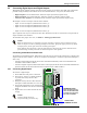
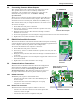
3.2.4 Connecting Control Relay Outputs
To connect a control relay output:
1. Turn OFF electrical power to the AC8.
2. If necessary, remove a conduit knockout to
permit wire entry into the AC8 enclosure.
3. Bring the wire(s) into the AC8 enclosure
through a conduit knockout or access slot.
4. Loosen the appropriate screw and slip the
stripped end of the wire into the terminal
block.
5. Tighten the screw until it holds the wire
snugly.
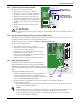
3.2.5 Connecting the Emergency Power Operation (EPOP) Input
The emergency power operation, or EPOP, input connector block (TB1) is at the bottom right corner of
the AC8 printed circuit board, just below the digital inputs.
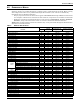
To determine the proper wire size, see Table 4 - Wiring specifications.
To connect to the EPOP input:
1. Turn OFF electrical power to the AC8.
2. If necessary, remove a conduit knockout to permit
wire entry into the AC8 enclosure.
3. Bring the wire into the AC8 enclosure through a
conduit knockout or access slot.
4. Loosen each screw and slip the stripped end of the
wire into the terminal block.
5. Tighten each screw until it holds the wire snugly.
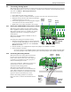
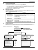
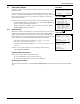
3.2.6 Setting the EPOP Jumper
The EPOP contact input has an associated jumper to
enable or disable emergency power operation (EPOP).
The AC8 comes from the factory with the EPOP jumper in
the Disabled position (DIS); it may be changed to Enabled
(EN).
To change the EPOP jumper setting:
1. Find the black EPOP jumper on the circuit board, as
shown at right. The jumper is at the bottom right
corner of the board just below the EPOP contact input
(see 1.7 - Controller Board Overview).
2. Decide whether your configuration requires the jumper to be enabled or disabled.
3. Set the jumper as needed:
• To enable EPOP, place the black jumper on the middle and right pins. The right side of the
jumper is labeled EN for Enabled.
• To disable EPOP, place the black jumper on the middle and left pins. The left side of the
jumper is labeled DIS for Disabled.
!
CAUTION
To reduce the risk of fire or electric shock, do not interconnect the outputs of different Class 2
circuits.
NOTE
When the EPOP jumper is set to Enabled, a Normally Closed contact must be attached or an
alarm will be generated and the outputs will default to the EPOP operation setting.
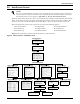
RELAY
OUTPUTS
TB4:
(BOTTOM)
2
(BOTTOM)
(TOP)
8
NC
C
NO
NC
C
NO
ON
PFM3
O
FF
ON
PFM8
OFF
NUMBERING KEYS -
Relay 1 at left (green);
Relay 2 at right (black)
RELAY OUTPUT
TERMINAL BLOCKS
TB2:
CONTACT
INPUTS
ASS
EPOP
EPOP INPUT
EPOP
P19
TB1
DIS EN
REV
ON
ON
PFM5
OFF
1
5
(BOTTOM)
(TOP)
4
3
2
1
8
7
6
5
TB1: EPOP
CONTACT
INPUT
TB1, TB2 INPUTS:
DRY CONTACTS ONLY.
ON
P
F
EPOP
jumper
EPOP
input