Liebert® Mini-Mate2™–5-Ton (17.
TABLE OF CONTENTS 1.0 INTRODUCTION . . . . . . . . . . . . . . . . . . . . . . . . . . . . . . . . . . . . . . . . . . . . . . . . . . . . . . . . . .1 1.1 Designed to Match Computer and Electronic Equipment Needs—From Installation to Operation . . . . . . . . . . . . . . . . . . . . . . . . . . . . . . . . . . . . . . . . . . . . . . . . . . . . . . . . . . . . . . . . 1 2.0 STANDARD FEATURES—5 TON SYSTEMS . . . . . . . . . . . . . . . . . . . . . . . . . . . . . . . . . . . . . .2 2.
FIGURES Figure 1 Figure 2 Figure 3 Figure 4 Figure 5 Figure 6 Figure 7 Figure 8 Figure 9 Figure 10 Figure 11 Figure 12 Figure 13 Figure 14 Figure 15 Figure 16 Figure 17 Figure 18 Figure 19 Figure 20 Figure 21 Figure 22 Figure 23 Wall-box . . . . . . . . . . . . . . . . . . . . . . . . . . . . . . . . . . . . . . . . . . . . . . . . . . . . . . . . . . . . . . . . . . . . . . . . 3 Free-cooling arrangement. . . . . . . . . . . . . . . . . . . . . . . . . . . . . . . . . . . . . . . . . . . . . . . . . . . .
TABLES Table 1 Table 2 Table 3 Table 4 Table 5 Table 6 Table 7 Table 8 Table 9 Table 10 Table 11 Table 12 Table 13 Table 14 Table 15 Table 16 Table 17 Table 18 Table 19 Table 20 Table 21 Table 22 Table 23 Table 24 Table 25 Table 26 Air-cooled data, 60Hz . . . . . . . . . . . . . . . . . . . . . . . . . . . . . . . . . . . . . . . . . . . . . . . . . . . . . . . . . . . . Air-cooled data, 50Hz . . . . . . . . . . . . . . . . . . . . . . . . . . . . . . . . . . . . . . . . . . . . . . . . . . . . . . . . . .
iv
Introduction 1.0 INTRODUCTION 1.1 Designed to Match Computer and Electronic Equipment Needs—From Installation to Operation Installed above the ceiling, Liebert Mini-Mate2 Precision Cooling systems control the cooling, humidity and air distribution required by sensitive electronic equipment. A range of sizes and configurations is available to meet varying sites’ needs. The Liebert Mini-Mate2 is also easy to use.
Standard Features—5 Ton Systems 2.0 STANDARD FEATURES—5 TON SYSTEMS 2.1 Evaporator Section—Split System The evaporator section is designed for ceiling installation. The cabinet and chassis are constructed of heavy gauge galvanized steel. The unit can be serviced using only one side increasing its versatility in mounting locations. Mounting brackets are factory-attached to the cabinet. Internal cabinet insulation meets ASHRAE 62.
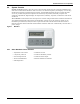
Standard Features—5 Ton Systems 2.4 System Controls System controls include a microprocessor control board mounted in the evaporator/chilled water unit and a wall-mounted interface with a two-line, 16-character liquid crystal display. A seven-key, membrane keypad for setpoint/program control, unit On/Off and alarm silence is below the LCD screen.
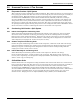
Optional Factory-Installed Features - Evaporator/Chilled Water Units 3.0 OPTIONAL FACTORY-INSTALLED FEATURES - EVAPORATOR/CHILLED WATER UNITS 3.1 Reheat Electric Reheat includes 304/304 stainless steel finned tubular reheat elements, with high limit safety switch. SCR Electric Reheat uses an SCR controller and unit control software to provide full cooling with modulating of the electric reheat elements to control air temperatures. Reheat capacity is up-sized to offset the cooling capacity.
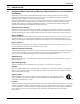
Optional Factory-Installed Features - Evaporator/Chilled Water Units 3.5 Free-Cooling Free-cooling option includes separate cooling coil, three-way slow-close valve and separate supply and return piping. Free-cooling is activated when the water temperature reaches a field-adjustable temperature, typically 45°F (7°C). The valve is rated for 300psi (2068kPa) working pressure.
Optional Factory-Installed Features - Evaporator/Chilled Water Units 3.8 Optional Configurations—Chilled Water Units Chilled Water Units are also available with the following valve options: • Three-way, slow-close, motorized chilled water valve rated for 300 psi (2068kPa) working pressure. Valve is non-spring return. • Two-way modulating chilled water valve, rated for 400psi (2758kPa) operating pressure, 72psi (496kPa) close-off rating. Valve is non-spring return.
Ship-Loose Accessories—Field-Installed 4.0 SHIP-LOOSE ACCESSORIES—FIELD-INSTALLED Filter Box includes filter box with 1" (25.4mm) duct flange connection, quantity 2, 20" x 20" x 4" nominal (508mm x 508mm x 102mm) filters and a 1" (25.4 mm) duct flange for use on the supply air opening. Filters are MERV 8 efficiency per ASHRAE Standard 52.2-2007. Condensate Pump is equipped with a discharge check valve.
Ship-Loose Accessories—Field-Installed Liebert SiteScan® is a monitoring solution that gives you decision-making power to effectively manage the equipment critical to your business. Liebert SiteScan enables communication from Liebert Precision Cooling and Power Protection units, as well as many other pieces of analog or digital equipment, to a front-end software package that provides real-time status and alarms so you can react quickly to changing situations.
Flexible Configurations 5.
Air-Cooled Systems—Capacities and Dimensions 6.0 Table 1 AIR-COOLED SYSTEMS—CAPACITIES AND DIMENSIONS Air-cooled data, 60Hz With Outdoor Condensing Unit With Centrifugal Condensing Unit Evaporator Model MMD60E or MMD60K Condensing Unit Type PFH - Outdoor MCD - Indoor DX Evaporator- Net Capacity Data - kW (Btuh) Total 19.2 (65,400) 19.3 (65,700) 80°F DB, 62.8°F WB (26.7°C DB, 17.1°C WB) 38% RH Sensible 18.5 (63,000) 18.5 (63,200) Total 18.4 (62,700) 18.5 (63,000) 75°F DB, 61°F WB (23.9°C DB, 16.
Air-Cooled Systems—Capacities and Dimensions Table 2 Air-cooled data, 50Hz Evaporator Model Condensing Unit Type DX Evaporator- Net Capacity Data, kW (Btuh) Total 80°F DB, 62.8°F WB (26.7°C DB, 17.1°C WB) 38% RH Sensible Total 75°F DB, 61°F WB (23.9°C DB, 16.1°C WB) 45% RH Sensible Total 72°F DB, 60°F WB (22.2°C DB, 15.
Air-Cooled Systems—Capacities and Dimensions Figure 4 General arrangement diagram, air-cooled split systems Condenser Coil Scroll Compressor High-Pressure Switch Hot Gas Bypass Solenoid Valve Liquid Injection Valve Bulb Suction Line Male Quick Connect Coupling Suction Line Female Quick * Connect Coupling Sensing Bulb External Equalizer 3-Way Head Pressure Relief Valve Hot Gas Bypass Control Valve 3/8" SAE 45° Male Flare (MCD) or Atmospheric (PFH) Pressure Relief Valve Check Valve Sight Glass Li
Air-Cooled Systems—Capacities and Dimensions Figure 6 Dimensions—Evaporator module Optional Discharge Air Duct Flange Supplied when Optional Filter Box is Ordered 46-1/2" (1181.1mm) Cabinet Dimension Air Outlet 14 1/2" (368.3mm) 13-3/8" (339.7mm) Air Inlet 13-3/8" (339.7mm) 7-5/8" (193.5mm) 3-1/8" (79.4mm) 14-1/2" (368.3mm) 24" (610mm) Cabinet Dimension 22-7/16 " Removable Access Panels 7/8" (22mm) Holes for Module Rigging (typ. 2 each end) (570mm) 13/16" (20.6mm) 1-1/8 " (28.
Air-Cooled Systems—Capacities and Dimensions Figure 7 Dimensions—Indoor air-cooled condensing module 54" (1371.6mm) Cabinet Dimension Field-supplied threaded rods for module support from ceiling (typ. 4) 1-5/8" (41.1mm) 32" (812.8mm) Cabinet Dimension 15-3/4" (400mm) 8-15/16" (227mm) 48" (1219.2mm) 3-3/8" (85.7mm) 14-1/2" (368.3mm) 24" (610mm) Cabinet Dimension 21-1/4" (539.8mm) 1-3/4" (44.5mm) 33-5/8" (854.
Air-Cooled Systems—Capacities and Dimensions Figure 8 Dimensions—Air-cooled systems, standard ambient outdoor condensing module Fan Rotation Counteclockwise (left side) Removable (Right) Panel for Access to Refrigeration Component Right Air Discharge 53" (1343mm) Left Air Intake 36-1/4" (918mm) C18" (457mm) Shaded area indicates a minimum clearance of 18" (457mm) for proper air flow Table 5 Removable front panel for access to high-voltage and low-voltage connections and to refrigeration components
Air-Cooled Systems—Capacities and Dimensions Figure 9 Dimensions—Air-cooled systems, high ambient and Quiet-Line condensing module Guard Height 5-1/2" (140mm) Top Air Discharge Right Air Intake 36-1/4" (918) Left Air Intake Shaded area indicates a minimum clearance of 18" (457mm) for proper air flow 2" (51mm) 53" (1346mm) Shaded area indicates a minimum clearance of 18" (457mm) for proper air flow Table 6 38-1/2" (978) Removable front panel for access to high-voltage and low-voltage connections a
Water/Glycol-Cooled Systems—Capacities and Dimensions 7.0 Table 7 WATER/GLYCOL-COOLED SYSTEMS—CAPACITIES AND DIMENSIONS Water/glycol data, 60Hz MMD60E or MMD60K Water-Cooled Glycol-Cooled Evaporator Model Condensing Unit Fluid Net Capacity Data DX Evaporator, kW (Btuh) 80°F DB, 62.8°F WB (26.7°C DB, 17.1°C WB) 38% RH 75°F DB, 61°F WB (23.9°C DB, 16.1°C WB) 45% RH 72°F DB, 60°F WB (22.2°C DB, 15.5°C WB) 50% RH Total Sensible Total Sensible Total Sensible 21.5 (73,500) 19.6 (67,000) 20.8 (70,800) 17.
Water/Glycol-Cooled Systems—Capacities and Dimensions Table 8 Water/glycol data, 50Hz Evaporator Model Condensing Unit Fluid Net Capacity Data DX Evaporator- kW (Btuh) 80°F DB, 62.8°F WB (26.7°C DB, 17.1°C WB) 38% RH 75°F DB, 61°F WB (23.9°C DB, 16.1°C WB) 45% RH 72°F DB, 60°F WB (22.2°C DB, 15.5°C WB) 50% RH Water-Cooled Total Sensible Total Sensible Total Sensible 20.7 (70,700) 19.3 (65,700) 19.9 (68,000) 17.1 (58,300) 19.5 (66,500) 15.7 (53,700) MMD59E or MMD59K Glycol-Cooled 16.9 (57,800) 16.
Water/Glycol-Cooled Systems—Capacities and Dimensions Figure 10 General arrangement diagram water/glycol split systems Scroll Compressor High-Pressure Switch Liquid Injection Valve Bulb Suction Line Male Quick Connect Coupling External Equalizer Tube-in-Tube Condenser Hot Gas Bypass Solenoid Valve Tube-in-Tube Condenser ass Byp Gas alve t o H tr o l V Con Suction Line Female Quick * Connect Coupling Sensing Bulb Water/Glycol Return Line Water/Glycol Fluid Return Supply Line Liquid Injection Valv
Water/Glycol-Cooled Systems—Capacities and Dimensions Figure 12 Dimensions—Evaporator module Optional Discharge Air Duct Flange Supplied when Optional Filter Box is Ordered 46-1/2" (1181.1mm) Cabinet Dimension Air Outlet 14 1/2" (368.3mm) 13-3/8" (339.7mm) Air Inlet 13-3/8" (339.7mm) 7-5/8" (193.5mm) 3-1/8" (79.4mm) 14-1/2" (368.3mm) 24" (610mm) Cabinet Dimension 22-7/16 " Removable Access Panels 7/8" (22mm) Holes for Module Rigging (typ. 2 each end) (570mm) 13/16" (20.6mm) 1-1/8 " (28.
Water/Glycol-Cooled Systems—Capacities and Dimensions Figure 13 Dimensions—Water/glycol-cooled indoor condensing unit NOTE: Unit is evenly spaced in reference to threaded rod centers. 32" (812.8mm) Cabinet Dimension 32" (812.8mm) Cabinet Dimension Field-supplied threaded rods for module support from ceiling typ. 4). Removable Access Panel 1/2" (12.7mm) dia. holes for module rigging (typ.
Chilled Water Systems—Capacities and Dimensions 8.0 CHILLED WATER SYSTEMS—CAPACITIES AND DIMENSIONS Table 11 Chilled water data, 60 & 50Hz MMD92C/MMD91C CW Model Net Capacity Data - kW (Btuh) based on 45°F (7.2°C) EWT & 10°F (5.6°C) temperature rise Total 20.1 (68,700) 80°F DB, 62.8°F WB (26.7°C DB, 17.1°C WB) 38% RH Sensible 18.7 (63,900) Flow Rate - GPM (l/m) 14.6 (55.3) Pressure Drop - ft. water (kPa) 18.7 (55.9) Total 16.3(55,600) 75°F DB, 61°F WB (23.9°C DB, 16.1°C WB) 45% RH Sensible 15.
Chilled Water Systems—Capacities and Dimensions Table 12 Capacity correction factors for MMD91C & MMD92C based on 10°F (5.6°C) water rise 72°F (22.2°C) 50% RH 75°F (23.9°C) 45%RH EWT TCC SCC TCC SCC 42°F (5.6°C) 1.28 1.14 1.23 1.12 43°F (6.1°C) 1.18 1.09 1.14 1.07 44°F (6.7°C) 1.09 1.05 1.07 1.03 45°F (7.2°C) 1.00 1.00 1.00 1.00 46°F (7.8°C) 0.92 0.95 0.93 0.96 47°F (8.3°C) 0.85 0.90 0.87 0.92 48°F (8.9°C) 0.79 0.85 0.81 0.88 49°F (9.4°C) 0.73 0.79 0.77 0.
Chilled Water Systems—Capacities and Dimensions Figure 16 Dimensions—Chilled water module Optional Discharge Air Duct Flange Supplied when Optional Filter Box is Ordered 46-1/2" (1181.1mm) Cabinet Dimension Air Outlet 14 1/2" (368.3mm) 13-3/8" (339.7mm) Air Inlet 13-3/8" (339.7mm) 7-5/8" (193.5mm) 3-1/8" (79.4mm) 14-1/2" Removable (368.3mm) Access Panels 24" (610mm) Cabinet Dimension 22-7/16 " 7/8" (22mm) Holes for Module Rigging (typ. 2 each end) (570mm) 13/16" (20.6mm) 1-1/8 " (28.
Electrical Data 9.0 ELECTRICAL DATA Table 14 Evaporator and chilled water electrical data, standard 1.5hp motor Base Evaporator Model Number 208-3-60 230-3-60 460-3-60 575-3-60 380/415-3-50 MMD60E/K MMD92C MMD60E/K MMD92C MMD60E/K MMD92C MMD60E/K MMD92C MMD59E/K MMD91C Cooling Only FLA 5.6 5.6 2.8 2 3.2 WSA 7.0 7.0 3.5 2.5 N/A OPD 15 15 15 15 N/A with Electric Reheat FLA 33.4 30.7 15.4 12.0 17.6 WSA 41.8 38.4 19.3 15.
Electrical Data Table 15 Evaporator and chilled water electrical data, optional 2hp motor Base Evaporator Model Number Cooling Only 208-3-60 230-3-60 460-3-60 575-3-60 380/415-3-50 MMD60E/K MMD92C MMD60E/K MMD92C MMD60E/K MMD92C MMD60E/K MMD92C MMD59E/K MMD91C 5.8 7.3 15 5.8 7.3 15 2.9 3.6 15 2.3 2.9 15 3.7 N/A N/A 33.6 42.0 45 30.9 38.6 40 15.5 19.4 20 12.3 15.4 20 18.1 N/A N/A 7.3 9.1 15 5.8 7.3 15 8.8 N/A N/A 19.9 24.9 25 MMD60E only 15.8 19.8 20 MMD60E only 23.
Electrical Data Table 18 Single-point power kit, air-cooled split system electrical data, standard 1.5hp motor 208-3-60 230-3-60 460-3-60 575-3-60 380/415-3-50 MMD60E/K MMD60E/K MMD60E/K MMD60E/K MMD590E/K MCD65A MCD65A MCD65A MCD65A MCD64A FLA 32.1 32.1 15.7 11.7 16.9 WSA 37.3 37.3 18.2 13.6 N/A OPD 50 50 25 20 N/A FLA 59.9 57.2 28.3 21.7 31.3 WSA 72.0 68.7 34.0 26.1 N/A OPD 80 80 40 30 N/A FLA 41.9 41.0 20.1 15.2 22.0 WSA 47.1 46.2 22.6 17.
Electrical Data Table 19 Single-point power kit, air-cooled split system electrical data, optional 2hp motor 208-3-60 230-3-60 460-3-60 575-3-60 380/415-3-50 MMD60E/K MMD60E/K MMD60E/K MMD60E/K MMD590E/K MCD65A MCD65A MCD65A MCD65A MCD64A FLA 32.3 32.3 15.8 12.0 17.4 WSA 37.5 37.5 18.3 13.9 N/A OPD 50 50 25 20 N/A FLA 60.1 57.4 28.4 22.0 31.8 WSA 72.2 68.9 34.1 26.4 N/A OPD 80 80 40 30 N/A FLA 42.1 41.2 20.2 15.5 22.5 WSA 47.3 46.4 22.7 17.
Electrical Data Table 20 Single-point power kit water/glycol-cooled split system electrical data, standard 1.5hp motor 208-3-60 230-3-60 460-3-60 575-3-60 380/415-3-50 MMD60E/K MMD60E/K MMD60E/K MMD60E/K MMD59E/K MCD69W MCD69W MCD69W MCD69W MCD68W FLA 26.3 26.3 12.8 9.4 13.2 WSA 31.5 31.5 15.3 11.3 N/A OPD 50 50 25 15 N/A FLA 54.1 51.4 25.4 19.4 27.6 WSA 66.2 62.9 31.1 23.
Electrical Data Table 21 Single-point power kit water/glycol-cooled split system electrical data, optional 2hp motor 208-3-60 230-3-60 460-3-60 575-3-60 380/415-3-50 MMD60E/K MMD60E/K MMD60E/K MMD60E/K MMD59E/K MCD69W MCD69W MCD69W MCD69W MCD68W FLA 26.5 26.5 12.9 9.7 13.7 WSA 31.7 31.7 15.4 11.6 N/A OPD 50 50 25 15 N/A FLA 54.3 51.6 25.5 19.7 28.1 WSA 66.4 63.1 31.2 24.1 N/A OPD 80 70 35 25 N/A Optional 2.
Refrigerant Piping 10.0 REFRIGERANT PIPING Table 22 Refrigerant charge Model # 60Hz 50Hz R-407C, oz (kg) MM*60E MM*59E 4 (0.11) MM*60K MM*59K 4 (0.11) MC*65A MC*64A 432 (12.3) MC*69W MC*68W PFH067A-_L7 PFH066A-_L7 426 (12.1) 94 (2.7) PFH067A-_H7 PFH066A-_H7 827 (23.4) PFHZ67A-_L7 PFHZ66A-_L7 827 (23.4) All evaporator units and condensing units are fully factory-charged with refrigerant.
Refrigerant Piping Table 26 Equivalent lengths for various pipe fittings, ft (m) Copper Pipe OD, in. 90 Degree Elbow Copper 90 Degree Elbow Cast 45 Degree Elbow Tee Gate Valve Globe Valve Angle Valve 1/2 0.8 (0.24) 1.3 (0.39) 0.4 (0.12) 2.5 (0.76) 0.26 (0.07) 7.0 (2.13) 4.0 (1.21) 5/8 0.9 (0.27) 1.4 (0.42) 0.5 (0.15) 2.5 (0.76) 0.28 (0.08) 9.5 (2.89) 5.0 (1.52) 3/4 1.0 (0.3) 1.5 (0.45) 0.6 (0.18) 2.5 (0.76) 0.3 (0.09) 12.0 (3.65) 6.5 (1.98) 7/8 1.45 (0.44) 1.8 (0.54) 0.
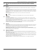
Glycol Loop Piping 11.0 GLYCOL LOOP PIPING Contact Emerson Application Engineering for assistance in choosing correct drycooler models. Refer to Figure 18. Figure 18 Heat rejection loop, multiple drycoolers and multiple indoor units Expansion Tank ______ Gal. (L) HP GPM (l/s) ft. ____(kW) ____ Per Pump @ ____(kPa) FS PUMP PACKAGE Drycooler No.
Model Number Nomenclature—All Systems 12.
Model Number Nomenclature—All Systems Figure 21 Air-cooled systems—outdoor prop fan condensing units PFH = Prop Fan Condensing Unit w/HGBP 0 = Standard Sound Level Z = Quiet-Line Nominal Capacity, kBtuh PFH 0 67 A - A L 7 A = Air-Cooled Unit 7 = R-407C Refrigerant L = 95°F (35°C) Ambient Liebert Lee-Temp™ H = 105°F (41°C) Ambient Liebert Lee-Temp - = Standard Coil C = Coated Coil A = 460V – 3ph-60Hz B = 575V – 3ph-60Hz Y = 208/230V – 3ph-60Hz M = 380/415V – 3ph-50Hz Figure 22 Water/glycol-cooled syste
Model Number Nomenclature—All Systems Figure 23 Chilled water systems M = Liebert Mini-Mate2 M= Microprocessor Control D = Disconnect Switch 0 = No Disconnect Switch Nominal Capacity (kBtuh) C = Chilled Water M M D 92 C 2 C H E L A 2 = 2-Way Chilled Water Valve (Motorized On/Off) 3 = 3-Way Chilled Water Valve (Motorized On/Off) D = 2-Way Chilled Water Valve (Modulating) T = 3-Way Chilled Water Valve (Modulating) A = 460V – 3ph-60Hz B = 575V – 3ph-60Hz C = 208V – 3ph-60Hz D = 230V – 3ph-60Hz M= 380/415V –
Guide Specifications for Liebert Mini-Mate2- 5-Ton Systems GUIDE SPECIFICATIONS FOR LIEBERT MINI-MATE2- 5-TON SYSTEMS 1.0 General 1.1 Summary These specifications describe requirements for an environmental control system. The system shall be designed to control temperature and relative humidity conditions within the room. The manufacturer shall design and furnish all equipment in the quantities and configurations shown on the project drawings.
Guide Specifications for Liebert Mini-Mate2- 5-Ton Systems 2.0 Product 2.1 Standard Features/ All Systems 2.1.1 Evaporator Cabinet Construction The cabinet and chassis shall be constructed of heavy gauge galvanized steel, and shall be serviceable from one side. Mounting brackets shall be factory-attached to the cabinet. Internal cabinet insulation shall meet ASHRAE 62.1 requirements for Mold Growth, Humidity & Erosion, tested per UL 181 & ASTM 1338 standards. 2.1.
Guide Specifications for Liebert Mini-Mate2- 5-Ton Systems 2.1.3.3.5 System Auto Restart For startup after power failure, the system shall provide automatic restart with a programmable (up to 9.9 minutes in 6-second increments) time delay. Programming can be performed either at the wallmounted controller or from the central site monitoring system. 2.1.4 Alarms 2.1.4.
Guide Specifications for Liebert Mini-Mate2- 5-Ton Systems 2.2 2.2.1 Direct Expansion System Evaporator Components Direct Expansion Coil The evaporator section shall include evaporator coil, thermostatic expansion valve and filter drier. The evaporator coil shall have 5.6 sq.ft. (0.52 sq.m) face area, four rows deep. It shall be constructed of copper tubes and aluminum fins and have a maximum face velocity of 444 FPM (2.26 m/s) at 2500 CFM (4248 CMH).
Guide Specifications for Liebert Mini-Mate2- 5-Ton Systems 2.3 Outdoor Air-Cooled Prop Fan Condensing Unit Condensing unit components shall include a condenser coil, a direct-drive propeller-type fan, a scroll compressor, high pressure switch, Liebert Lee-Temp™ receiver and head pressure control valve, hot gas bypass system and liquid line solenoid valve. A hot gas bypass system shall be provided to reduce compressor cycling and improve operation under low load conditions.
Guide Specifications for Liebert Mini-Mate2- 5-Ton Systems 2.4.4 SCR Electric Reheat The electric reheat shall be low-watt density, 304/304 stainless steel, finned-tubular and shall be capable of maintaining room dry bulb conditions when the system is calling for dehumidification. The reheat section shall include an agency-approved safety switch to protect the system from overheating.
Guide Specifications for Liebert Mini-Mate2- 5-Ton Systems 2.5.4 Condensate Pump Bracket A condensate pump bracket shall be provided to mount condensate pump directly to the end of the unit, allowing for easier installation and alignment of the condensate pump. 2.5.5 Refrigerant Line Sweat Adapter Kit 2.5.6 Single Point Power Kit Provide a sweat adapter kit to permit field brazing of refrigerant line connections.
Guide Specifications for Liebert Mini-Mate2- 5-Ton Systems 3.0 Execution 3.1 Installation of Air Conditioning Unit 3.1.1 General Install air conditioning unit in accordance with manufacturer’s installation instructions. Install unit plumb and level, firmly anchored to support the unit’s weight in location indicated and maintain manufacturer’s recommended clearances.
Technical Support / Service Web Site www.liebert.com Monitoring liebert.monitoring@emerson.com 800-222-5877 Outside North America: +00800 1155 4499 Single-Phase UPS & Server Cabinets liebert.upstech@emerson.