READ AND SAVE THESE INSTRUCTIONS CALLAN™ 48” Ceiling Fan Owner's Manual Model Numbers CF110BS00 - Brushed Steel CF110ORB00 - Oil Rubbed Bronze Net Weight: 23.7 Lbs. Questions, problems, missing parts: Before returning to the store call Emerson Electric Customer Service 8 a.m. - 6 p.m., EST, Monday-Friday Part No. F40BP74660000 11/12 1-800-654-3545 www.emersonfans.com Form No. BP7466 ETL Model No.
READ AND SAVE THESE INSTRUCTIONS Safety Instructions ! 3. The outlet box and joist must be securely mounted and capable of reliably supporting at least 50 pounds. Use only U.L. outlet boxes listed as “Acceptable for Fan Support of 15.9kg. (35 lbs.) or less”., and use the mounting screws provided with the outlet box. Most outlet boxes commonly used for support of light fixtures are not acceptable for fan support and may need to be replaced. Consult a qualified electrician if in doubt. 4.
Unpacking Instructions PACKAGE CONTENTS WARNING ! Do not install or use fan if any part is damaged or missing.
This Manual Is Designed to Make it as Easy as Possible for You to Assemble, Install, Operate and Maintain Your Ceiling Fan Installed Wire Length Up to 50 ft. 50-100 ft. Tools Needed for Assembly One Phillips head screwdriver One 1/4” blade screwdriver One stepladder One wire stripper ! Materials Wire Size A.W.G. 14 12 WARNING Before assembly your ceiling fan, refer to section on proper method of wiring your fan (page 9).
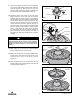
NOTE: Take care not to scratch fan housing when installing blades. FLANGE/BLADE ASSEMBLY 1/4-20 x 1/2" FLANGE SCREWS WITH LOCKWASHERS PRE-ASSEMBLED (2) MOTOR HUB 4. Attach the flange/blade assembly to the motor hub using the two pre-installed 1/4-20 x 1/2” flange screws and lockwashers. Make sure the screws are tightened securely (Figure 4). Repeat this procedure for the other four blade assemblies. 5. Screw the finial onto the center threaded stud of the motor housing until securely tighten (Figure 5).
9. Remove the hanger ball by loosening the setscrew in the hanger ball until the ball falls freely down the downrod (Figure 8). Remove the pin from the downrod, then remove the hanger ball. Retain the pin and hanger ball for reinstallation in Step 14. PIN HANGER BALL SETSCREW 10. Separate, untwist and unkink the two 80” motor leads. Route the motor lead wires through the downrod. Align the clevis pin holes in the downrod with the holes in the motor coupler.
14. Reinstall the hanger ball (Figure 12) on the downrod as follows. Route the three 80” motor leads through the hanger ball. Position the pin through the two holes in the downrod and align the hanger ball so the pin is captured in the groove in the top of the hanger ball. Pull the hanger ball up tight against the pin and securely tighten the setscrew in the hanger ball. A loose setscrew could create fan wobble.
How to Hang Your Ceiling Fan ! WARNING CEILING Turning off wall switch is not sufficient. To avoid possible electrical shock, be sure electricity is turned off at the main fuse box before wiring. All wiring must be in accordance with National and Local codes and the ceiling fan must be properly grounded as a precaution against possible electrical shock. AT LEAST 7' CAUTION: To reduce the risk of electrical shock, disconnect the electrical supply circuit before installing the fan, light kit or receiver.
How to Wire Your Ceiling Fan If you feel that you do not have enough electrical wiring knowledge or experience, have your fan installed by a licensed electrician. 1. Connect the green grounding lead from the hanger ball and the green grounding lead from the hanger bracket to the grounding conductor of supply (this may be a bare wire or wire with green colored insulation). Securely connect wires with wire connectors supplied. (Figure 16.
Wall Control Installation ! WARNING Turning off wall switch is not sufficient. To avoid possible electrical shock, be sure electricity is turned off at the main fuse box before wiring. All wiring must be in accordance with National and Local codes and the ceiling fan must be properly grounded as a precaution against possible electrical shock. 4 3 2 CAUTION: To reduce the risk of electrical shock, disconnect the electrical supply circuit before installing the fan, light kit or receiver.
8. Position the faceplate (provided) onto the SW46 speed control. Using the two 6-32 x 1/4” screws, screw the faceplate and speed control to the wall outlet box (Figure 21). OUTLET BOX SW46 SPEED CONTROL 9. Restore power at the main fuse box or circuit breaker panel. 4 CAUTION 3 2 1 For fans equipped with built-in variable speed devices: These devices must be set at their MAXIMUM SPEED for proper operation. Adjustments to their setting must only be made with Quietslide in the OFF position.
Repair Parts 2 1 3 5 14 4 6 7 15 13 16 22 17 4 3 2 1 0 9 8 11 10 18 21 20 12 19 12 ETL Model No.
Repair Parts Listing Model Numbers Key No. Description CF110BS00 CF110ORB00 760750-17 760750-32 1 2 3 Hanger Ball Assembly, Consisting of: Hanger Bracket Hanger Ball Downrod, 4.
Maintenance IMPORTANT CARE INSTRUCTIONS for your Ceiling Fan ! WARNING Do not use water when cleaning your ceiling fan. It could damage the motor or the blades and create the possibility of an electrical shock. Periodic cleaning of your new ceiling fan is the only maintenance that is needed. When cleaning, use only a soft brush or lint free cloth to avoid scratching the finish. Abrasive cleaning agents are not required and should be avoided to prevent damage to finish. Accessories 1.
Emerson Air Comfort Ceiling Fan Limited Warranty What The Limited Warranty Covers: This limited warranty is offered by Air Comfort Products division of Emerson Electric Co. ("Emerson" "we" or "us") located at the address stated below to the original retail purchaser ("you" or "your") of an Emerson Air Comfort Ceiling Fan product ("Emerson Ceiling Fan") and covers the motor and the other components and accessories of the Emerson Ceiling Fan against all defects in workmanship and materials.
Air Comfort Products DIVISION OF EMERSON ELECTRIC CO. 8100 W. Florissant • St. Louis, MO 63136 Questions, problems, missing parts: Before returning to the store call Emerson Electric Customer Service 8 a.m. - 6 p.m., EST, Monday-Friday 1-800-654-3545 www.emersonfans.com Retain this manual for future use. Part No. F40BP74660000 11/12 Form No. BP7466 ETL Model No.