READ AND SAVE THESE INSTRUCTIONS 1895 TM ® TM Model No. CF1AB01 CF1PW01 CF1ORB01 CF1WB01 DATE CODE: The date code of this fan may be found on the box, stamped in ink on a white label. Max. Weight: 27.0 Lbs. With Blades You should record this data above and keep it in a safe place for future use. CORNERSTONE® Series Ceiling Fan Owner's Manual Part No. F40BP73270000 Form No. BP7327 U.L. Model No.
! WARNING WARNING: To avoid fire, shock, and serious personal injury, follow these instructions. Safety Instructions 1. Read your owner’s manual carefully and keep it for future reference. 2. Before servicing or cleaning unit, switch power off at service panel and lock service panel disconnecting means to prevent power from being switched on accidentally. When the service disconnecting means cannot be locked, securely fasten a warning device, such as a tag, to the service panel. 3.
NOTE: Before discarding packaging material, be certain all parts have been removed. Unpacking Instructions For your convenience, check-off boxes are provided next to each step. As each step is completed, place a check mark in the box. This will insure that all steps have been completed and will be helpful in finding your place should you be interrupted. ! FAN MOTOR AND HOUSING ASSEMBLY MOTOR COVER WARNING Do not install or use fan if any part is damaged or missing.
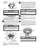
Assembly Instructions 1. Remove the fan motor and housing assembly from styrofoam packaging and position it so that the top of the motor is facing you. 2.Remove the hanger ball from the downrod by loosening the setscrew in the hanger ball until the ball falls freely down the downrod (Figure 1). Remove the pin from the downrod, then remove the hanger ball. Retain the pin and hanger ball for reinstallation in step 9.
7. If you have installed the 18” downrod, install the downrod trim and decorative bulb as follows (Figure 5). Slide the decorative trim (grommet-end first) over the downrod and seat the grommet firmly against the motor cover. Then slide the decorative bulb (oriented as shown) over the downrod, being certain that the downrod trim seats in the bottom grommet of the decorative bulb. 12.
How to Hang Your Ceiling Fan SWITCH HOUSING ASSEMBLY ! WARNING The fan must be hung with at least 7' of clearance from floor to blades (Figure 12). TURN TURN UPPER COVER TRIM CEILING HOLE FOR SPEED CONTROL SWITCH CHAIN 8-32 x1/2" SCREW (2) Figure 10 AT LEAST 7' LOOKING UP INTO SWITCH HOUSING ASSEMBLY FLOOR Figure 12 16. Position the lower trim assembly on the upper cover trim so that the tabs on the lower trim assembly slide into the slots in the upper cover trim (Figure 11).
NOTE: CEILING COVER, SUPPLY WIRES AND FAN WIRES OMITTED FOR CLARITY. 2. Securely connect the fan motor white wire to the supply white (neutral) wire using wire connector supplied (Figure 15). Securely connect the fan motor black wire and blue wire to the supply black (hot) wire using wire connector supplied (Figure 16).
Using Your Ceiling Fan Attaching Light Kit 1. Restore electrical power to the outlet box by turning the electricity on at the main fuse box. To install an accessory light kit, first unscrew the finial and remove the lower trim (Figure 18). Then remove the center trim by removing four 8-32 x 1/2” screws. Remove the threaded nipple from the center trim and install the light kit in accordance with the light kit Owner’s Manual. 2.
Maintenance Accessories IMPORTANT CARE INSTRUCTIONS for your Ceiling Fan 1. Ceiling Fan Light Kits (see store or catalog). 2. Downrod Extension Kits (see store or catalog). 3. Ceiling Fan Controls (see store or catalog). Periodic cleaning of your new ceiling fan is the only maintenance that is needed. When cleaning, use only a soft brush or lint free cloth to avoid scratching the finish.
Repair Parts Before discarding packaging material, be certain all parts have been removed. 2 How to Order Repair Parts 1 3 18 16 38 6 WHEN ORDERING REPAIR PARTS, ALWAYS GIVE THE FOLLOWING INFORMATION: 17 • PART NUMBER • PART DESCRIPTION 7 • NAME OF ITEM 18 19 15 19 20 37 • MODEL NUMBER For repair parts, phone 1-800-654-3545.
Repair Parts Listing Key No. — 1 2 3 6 Description Hanger Pack, Containing: Bracket, Hanger (1) Hanger Ball Assembly (1) Downrod (1) Ceiling Canopy Model No. CF1AB01 761655-3 — — — 761620-3 Part Numbers Model No. Model No. CF1ORB01 CF1PW01 761655-32 761655-22 — — — — — — 761620-33 761620-30 Model No.
LIMITED WARRANTY What The Warranty Covers: This warranty covers the motor and the other components and accessories of your Emerson ceiling fan against all defects in workmanship and materials. You must be the original purchaser or user of the product to be covered. What The Period Of Coverage Is: As it applies to the motor, this warranty will last for the lifetime of your ceiling fan. All other components and accessories are covered by this warranty for one year from the date you purchased your ceiling fan.