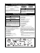
READ AND SAVE THESE INSTRUCTIONS HIGHPOINTE™ Ceiling Fan Owner's Manual Model Numbers CF205BS01 CF205GES01 CF205VS01 Brushed Nickel Finish with Opal Matte Glass and Dark Mahogany Blades Golden Espresso with Sandstone Glass and Chocolate Blades Net Weight: Part No. F40BP73750002 22.1 Vintage Steel with Vintage Cream Glass and Riverwash/Honey Oak Blades Lbs. Form No. BP7375-2 U.L. Model No.
WARNING ! WARNING: To avoid fire, shock, and serious personal injury, follow these instructions. Safety Instructions 1. Read your owner’s manual carefully and keep it for future reference. 2. Before servicing or cleaning unit, switch power off at service panel and lock service panel disconnecting means to prevent power from being switched on accidentally. When the service disconnecting means cannot be locked, securely fasten a warning device, such as a tag, to the service panel. 3.
This Manual Is Designed to Make it as Easy as Possible for You to Assemble, Install, Operate and Maintain Your Ceiling Fan Tools Needed for Assembly One Phillips head screwdriver One wire cutter Installed Wire Length Up to 50 ft. 50-100 ft. One stepladder One wire stripper WARNING ! MATERIALS Wiring outlet box and box connectors must be of type required by the local code. The minimum wire would be a 3-conductor (2-wire with ground) of the following size: Wire Size A.W.G.
General Your Emerson ceiling fan comes supplied with a Fan/Light Remote Control which consists of a remote control (transmitter) and a remote control receiver mounted under the ceiling cover. This system allows you to regulate your ceiling fan speed and light intensity. NOTE: An optional Emerson Electric SW406 Wall Control may also be used to control your ceiling fan. Electrical Requirements Your new ceiling fan will require a grounded electrical supply line of 120 volts AC, 60 Hz, 15 amp circuit.
How to Assembly Your Ceiling Fan Your ceiling fan can be assembled with the light kit and glass or without the light kit and glass. To assemble without the light kit and glass, you will use the no-light cover plate. In order to use the no-light cover plate, the light sockets will need to be removed from the light kit plate. (continued) LIGHT KIT PLATE BLACK WIRE BLUE WIRE FAN MOTOR/ HOUSING ASSEMBLY NOTE: In order to remove the light sockets, the wires on the light kit plate will need to be cut.
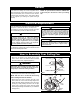
How to Assembly Your Ceiling Fan ! WARNING HAIRPIN CLIP It is critical that the clevis pin in the motor coupling is properly installed and the setscrews securely tightened. Failure to verify that the pin and setscrews are properly installed (as shown in Figure 6) could result in the fan falling. DOWNROD MOTOR COUPLING SETSCREW (2) REVERSE SWITCH 9. Tighten the setscrews (Figure 6) securely while pulling up on the downrod.
How to Assembly Your Ceiling Fan 13. Slide the rod support assembly up the downrod until the threaded holes in the rod support align with the holes in the decorative rod assemblies (Figure 9). Secure the decorative rods to the rod support using three decorative rod screws; do not tighten the rod screws at this time. DOWNROD ROD SUPPORT ASSEMBLY DECORATIVE ROD SCREW 14. Rotate the rod support assembly until the decorative rod assemblies are aligned vertically with the downrod (Figure 9).
How to Hang Your Ceiling Fan ! WARNING CEILING Turning off wall switch is not sufficient. To avoid possible electrical shock, be sure electricity is turned off at the main fuse box before wiring. All wiring must be in accordance with National and Local codes and the ceiling fan must be properly grounded as a precaution against possible electrical shock. AT LEAST 7' FLOOR ! Figure 11 WARNING The fan must be hung with at least 7' of clearance from floor to blades (Figure 11).
How to Wire Your Ceiling Fan 2. Refer to Figure 14 and 15 and connect the receiver wires to the supply wires and the fan motor wires as follows: If you feel that you do not have enough electrical wiring knowledge or experience, have your fan installed by a licensed electrician. ! a. Securely connect the green grounding wires from the hanger ball and the hanger bracket to the supply grounding conductor (this may be a bare wire or a wire with green insulation).
How to Wire Your Ceiling Fan TO 120VOLT SUPPLY STANDARD ON-OFF WALL SWITCH OR OPTIONAL SW406 WALL CONTROL BLACK BLACK (HOT) (continued) BLACK WHITE WHITE WHITE GROUND RED TWO-CONDUCTOR CABLE (WITH GROUND) BLUE WHITE BLACK BLUE WHITE GREEN WIRE (GROUND) FROM HANGER BALL AND HANGER BRACKET HANGER BALL Figure 15 ! WARNING CEILING COVER To avoid possible fire or shock, make sure that the electrical wires are completely inside the outlet box and not pinched between the ceiling cover and the ceil
How to Disassemble Your Light Kit for Cover Plate Assembly Only ! WARNING Turning off wall switch is not sufficient. To avoid possible electrical shock, be sure electricity is turned off at the main fuse box before wiring. All wiring must be in accordance with National and Local codes and the ceiling fan must be properly grounded as a precaution against possible electrical shock.
How to Disassemble Your Light Kit for Cover Plate Assembly Only (continued) 4. Carefully tuck blue and white wires from motor up into the fan motor/housing assembly (Figure 21). 5. Place the cover plate onto the fan motor/housing aligning the three flat areas on the top flange of the cover plate with the three pins on the inside of the fan motor/housing (Figure 21). Then turn the cover plate clockwise until it stops turning. 6. Your cover plate is now installed.
Remote Control Procedures (continued) Setting Operating Frequency of Transmitter COVER Your remote control transmitter has code switches which must be set in one of 32 possible code combinations. The five levers (numbered 1, 2, 3, 4, and 5) on the switches are factory-set in the ON (up) position. Do not use this setting. Change the switch settings as follows: WALL BRACKET SCREW HOLES (2) POWER INDICATOR LIGHT 1.
Trouble Shooting Remote Control Fan/Light Fails to Operate • Check that the speed switch on the fan is set to HIGH (....) speed. • Check that the light switch is on. • Check that the battery is good (blue indicator light should light when any button is pressed). • Check that the receiver is wired properly. • Check that code switches in the remote control and receiver are set in the same position.
Trouble Shooting ! WARNING: For your own safety, turn off power at fuse box or circuit breaker before trouble shooting your fan. TROUBLE 1. Fan will not start. PROBABLE CAUSE 1. Check main and branch circuit fuses or circuit breakers. 2. Loose power line connections to the fan, or loose switch wire connections in the switch housing. 2. Check line wire connections to fan and switch wire connections in the switch housing. ! WARNING: Make sure main power is turned OFF. 3.
Instruction to the User (if device contains a digital device) This equipment has been tested and found to comply with the limits for a class B digital device, pursuant to part 15 of the FCC Rules. These limits are designed to provide reasonable protection against harmful interference in a residential installation. This equipment generates, uses and can radiate radio frequency energy and if not installed and used in accordance with the instructions, may cause harmful interference to radio communications.
Notes 17 U.L. Model No.
Repair Parts 1 2 3 5 26 4 28 14 27 7 15 6 17 16 18 17 8 9 22 10 20 21 19 11 13 22 12 25 23 24 18 U.L. Model No.
Repair Parts Listing Model Numbers Key No.
Emerson Air Comfort Ceiling Fan Limited Warranty What The Limited Warranty Covers: This limited warranty is offered by Air Comfort Products division of Emerson Electric Co. ("Emerson" "we" or "us") located at the address stated below to the original retail purchaser ("you" or "your") of an Emerson Air Comfort Ceiling Fan product ("Emerson Ceiling Fan") and covers the motor and the other components and accessories of the Emerson Ceiling Fan against all defects in workmanship and materials.