READ AND SAVE THESE INSTRUCTIONS AMERICA’S FAN COMPANY 52" “APOLLO” Series Model No. CF3900WW01 CF3900PB01 CF3900HTW01 CF3900TG01 CF3900AW01 CF3900WPB01 CF3900BS01 CF3900CK01 Net Weight: 18.0 CF3900AB01 CF3900OB01 CF3900BQ01 Lbs. ® “APOLLO” Series Ceiling Fan Owner's Manual Part No. F40BP72340003 Form No.
LIMITED WARRANTY What The Warranty Covers: This warranty covers the motor and the other components and accessories of your Emerson ceiling fan against all defects in workmanship and materials. You must be the original purchaser or user of the product to be covered. What The Period Of Coverage Is: As it applies to the motor, this warranty will last for the lifetime from the date you purchased your ceiling fan.
! WARNING WARNING: To avoid fire, shock, and serious personal injury, follow these instructions. Safety Instructions 1. Read your owner’s manual carefully and keep it for future reference. 2. Before servicing or cleaning unit, switch power off at service panel and lock service panel disconnecting means to prevent power from being switched on accidentally. When the service disconnecting means cannot be locked, securely fasten a warning device, such as a tag, to the service panel. 3.
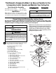
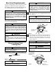
This Manual Is Designed to Make it as Easy as Possible for You to Assemble, Install, Operate and Maintain Your Ceiling Fan Installed Wire Length Up to 50 ft. 50-100 ft. Tools Needed for Assembly One Phillips head screwdriver Three wire connectors (supplied.) One stepladder One wire stripper ! MATERIALS Wiring outlet box and box connectors must be of type required by the local code. The minimum wire would be a 3-conductor (2-wire with ground) of the following size: Wire Size A.W.G.
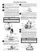
Assembly Instructions 1. Remove the fan motor and housing assembly from styrofoam packaging and position it so that the top of the motor is facing you. 2. Separate, untwist and unkink the three motor leads. Route the motor leads through the hanger ball/downrod assembly and seat the downrod in the motor coupling. 3. Align the clevis pin holes in the downrod with the holes in the motor coupling. Install the clevis pin and secure with the hairpin clip.
9. The fan comes with blue, black and white leads that are 80-inches long. Before installing fan, measure up approximately 6 to 9-inches above the ball/downrod assembly. Cut off excess leads and strip back insulation 1/2-inch from end of leads. 13. Remove the fan motor and housing assembly from the styrofoam packaging. Position the motor so that the bottom of the motor is facing you.
Electrical Requirements ! Your new ceiling fan will require a grounded electrical supply line of 120 volts AC, 60 Hz, 15 amp circuit. To reduce the risk of fire, electric shock, or personal injury, mount fan to outlet box marked acceptable for fan support, and use screws supplied with outlet box. Most outlet boxes commonly used for support of light fixtures are not acceptable for fan support and may need to be replaced. Consult a qualified electrician in in doubt.
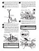
How to Wire Your Ceiling Fan 5. Secure the ceiling cover in place by sliding lockwashers over the threaded studs and installing the two knurled knobs (supplied). (Figure 5.) Tighten the knurled knobs securely until the ceiling cover fits snugly against the ceiling and the hole in the ceiling cover is clear of the downrod. Your fan is now wired to be turned on and off from the fan switch.
Attaching Light Kit ! Accessories 1. Ceiling Fan Light Kits (see store or catalog). 2. Ceiling Fan/Light Controls (see store or catalog). 3. Downrod Extension Kits (see store or catalog). WARNING To avoid possible electrical shock, be sure electricity is turned off at the main fuse box before wiring. ! To install an accessory light kit, remove the three screws securing the switch cup assembly to the fan, remove the switch cup assembly, and disconnect the connector.
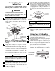
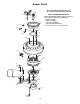
Repair Parts Before discarding packaging material, be certain all parts have been removed. 2 1 3 16 6 14 HOW TO ORDER REPAIR PARTS WHEN ORDERING REPAIR PARTS, ALWAYS GIVE THE FOLLOWING INFORMATION: • NAME OF ITEM • MODEL NUMBER • THE PART NUMBER • THE PART DESCRIPTION For repair parts, phone 1-800-654-3545.
762304 762020 — — — — — — — — — — — — — — — Cover, Ceiling Hub, Rubber Blade Assembly (Full set for one fan) Flange Set (Full set for one fan) Switch Cup Cover, Motor Motor Parts Bag, containing: Pin, Clevis (1) Clip, Hairpin (1) Coupling (1) Pendant (1) Wire Connector (3) Wrench, Hex, 3/16” (1) Stud, Threaded, 1-1/4” (2) Lockwasher (4) Knob, Knurled (4) Screw, 10-32 x 5/8" (11) Screw, Flat, 8-32 x 5/16" (4) Screw, 10-32 x 3/8" (16) Washer, Flat (16) Setscrew, (1) Stud, Threaded, 1” (2) Auxilia
! WARNING: FOR YOUR OWN SAFETY TURN OFF POWER AT FUSE BOX OR CIRCUIT BREAKER BEFORE TROUBLE SHOOTING YOUR FAN. Trouble Shooting TROUBLE 1. Fan will not start. PROBABLE CAUSE SUGGESTED REMEDY 1. Fuse or circuit breaker blown. 1. Check main and branch circuit fuses or circuit breakers. 2. Loose power line connections to the fan, or loose switch wire connections in the switch housing. 2. Check line wire connections to fan and switch wire connections in the switch housing. ! 2. Fan sounds noisy. 3.