
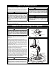
Exploded Parts


5
U.L. Model No.: CF4801 and CF4501
How to Put Your Ceiling Fan Together (continued)
6. Install the setscrew (supplied in loose parts bag) in
the motor coupling and tighten using the 5/32"
setscrew wrench (supplied) (Figure 3).
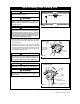
7. Screw two 1” threaded studs (provided) into the
motor (Figure 4). Leave approximately 7/8” of the
stud extending above the motor. Slide the motor
cover over the downrod and rotate the cover until
the threaded studs protrude; install two knurled
knobs (supplied) to secure the cover.
NOTE: Make sure the red and brown leads are
capped with wire connectors. Make sure the red,
brown, and yellow wires and wire connectors are
completely inside motor coupling cover and not
pinched between the motor coupling cover and
motor.
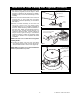
8. Position the ceiling cover over the downrod. Be
sure the cover is oriented correctly, with the large
opening at the top (Figure 5).
9. Reinstall the hanger ball on the downrod as
follows. Route the motor leads through the hanger
ball and slide the hanger ball over the downrod
(Figure 5). Install the pin through the holes at the
top of the downrod and slide the hanger ball up
the downrod, aligning the ball so the pin is
captured in the groove in the top of the hanger
ball. Pull the hanger ball up tight against the pin
and securely tighten the setscrew in the hanger
ball. A loose setscrew could create fan wobble.
10.The blue, black and white leads exiting the
downrod are 80-inches long. Before installing fan,
measure up approximately 6 to 9-inches above the
ball/downrod assembly. Cut off excess leads and
strip back insulation 1/2-inch from end of leads.
SETSCREW
DOWNROD
PIN
HANGER BALL
CEILING COVER
Figure 5
DOWNROD
SETSCREW
Figure 3
It is critical that the pin in the hanger ball is properly
installed and the setscrew securely tightened.
Failure to verify that the pin and setscrew are
properly installed could result in the fan falling.
WARNING
!
7/8"
RED LEAD
WIRE
CONNECTORS
KNURLED KNOB
1" THREADED
STUD
MOTOR
MOTOR
COUPLING
COVER
WIRE CONNECTOR
YELLOW LEADS
BROWN LEAD
Figure 4