READ AND SAVE THESE INSTRUCTIONS Fan Blades Not Included Ceiling Fan Owner's Manual PREMIUM™ SELECT CROWN™ SELECT Model Numbers Model Numbers CF4801AB00 CF4801AP00 CF4801BS00 CF4801CK00 CF4801GBZ00 CF4801GES00 CF4801ORB00 CF4801VNB00 CF4801WW00 CF4501AP00 CF4501GBZ00 CF4501GES00 CF4501VNB00 Net Weight: Part No. F40BP74470000 23.8 Lbs. Form No. BP7447 U.L. Model No.
! WARNING WARNING: To avoid fire, shock, and serious personal injury, follow these instructions. Safety Instructions 1. Read your owner’s manual carefully and keep it for future reference. 2. Before servicing or cleaning unit, switch power off at service panel and lock service panel disconnecting means to prevent power from being switched on accidentally. When the service disconnecting means cannot be locked, securely fasten a warning device, such as a tag, to the service panel. 3.
This Manual Is Designed to Make it as Easy as Possible for You to Assemble, Install, Operate and Maintain Your Ceiling Fan Installed Wire Length Up to 50 ft. 50-100 ft. Tools Needed for Assembly One Phillips head screwdriver One wire stripper One stepladder MATERIALS ! Wiring outlet box and box connectors must be of type required by the local code. The minimum wire would be a 3-conductor (2-wire with ground) of the following size: Wire Size A.W.G.
Electrical Requirements Your new ceiling fan will require a grounded electrical supply line of 120 volts AC, 60 Hz, 15 amp circuit. The outlet box must be securely anchored and capable of withstanding a load of at least 50 pounds. ! ! WARNING Turning off wall switch is not sufficient. To avoid possible electrical shock, be sure electricity is turned off at the main fuse box before wiring.
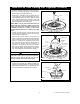
How to Put Your Ceiling Fan Together (continued) 6. Install the setscrew (supplied in loose parts bag) in the motor coupling and tighten using the 5/32" setscrew wrench (supplied) (Figure 3). 7. Screw two 1” threaded studs (provided) into the motor (Figure 4). Leave approximately 7/8” of the stud extending above the motor. Slide the motor cover over the downrod and rotate the cover until the threaded studs protrude; install two knurled knobs (supplied) to secure the cover.
How to Put Your Ceiling Fan Together (continued) 11. Use four #10-24 x 12mm pan head screws and flat washers (supplied) to secure flange to blade (Figure 6). Repeat for the remaining four blades. Illustration may not show the exact flange you are installing. #10-24 x 12mm PAN HEAD BLADE SCREW (4) FLAT WASHER (4) FAN BLADE (Sold Separately) 12. Use the 10 round recessed holes in the motor hub marked with "5" and install the five blade assemblies (ordered separately) in accordance with Step 13.
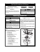
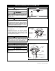
How to Hang Your Ceiling Fan ! WARNING CEILING The fan must be hung with at least 7' of clearance from floor to blades (Figure 9). ! WARNING AT LEAST 7' The outlet box and joist must be securely mounted and capable of supporting at least 50 lbs. Use only a U.L. outlet box listed as “Acceptable for Fan Support of 22.7 kg. (50 lbs.) or less”. FLOOR Figure 9 ! WARNING To reduce the risk of fire, electrical shock, or personal injury, mount fan to outlet box marked “Acceptable for Fan Support of 22.
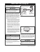
How to Wire Your Ceiling Fan If you feel that you do not have enough electrical wiring knowledge or experience, have your fan installed by a licensed electrician. EMERSON FAN CONTROL LISTED OUTLET BOX ! WARNING BLACK FAN WIRE RED BLACK GREEN WIRE (GROUND) FROM HANGER BRACKET To avoid possible electrical shock, be sure electricity is turned off at the main fuse box before wiring.
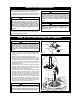
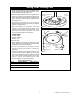
Using Your Ceiling Fan 1. Screw three 25-watt (maximum) candelabra base lamps (supplied) into the uplight sockets on top of the fan housing assembly (Figure 14). 25-WATT (Max.) CANDELABRA BASE LAMPS (3) 2. Slide the large pendant onto the the speed control pull chain, secure by connecting the coupling to the chain. Slide the pendant onto the accent light pull chain, secure by connecting the coupling to the chain. (Figure 15). UPLIGHT SOCKETS (3) 3. Assembly of the ceiling fan is now complete.
Attaching Optional Light Kit To install an Emerson accessory light kit, remove the three screws securing the switch cup assembly to the fan, remove the switch cup assembly, and disconnect the connector. Remove the screw plug from the bottom of the switch cup and install the light kit in accordance with the Emerson light kit Owner's Manual. ! WARNING To avoid possible electrical shock, be sure electricity is turned off at the main service box before wiring.
Trouble Shooting ! WARNING: For your own safety, turn off power at fuse box or circuit breaker before trouble shooting your fan. TROUBLE 1. Fan will not start. PROBABLE CAUSE 1. Fuse or circuit breaker blown. SUGGESTED REMEDY 1. Check main and branch circuit fuses or circuit breakers. ! 2. Loose power line connections to the fan, or loose switch wire connections in the switch housing. 2. Fan sounds noisy. 2. Check line wire connections to fan and switch wire connections in the switch housing. 1.
Repair Parts 2 1 3 16 6 14 15 18 17 13 18 31 32 28 24 5 4 27 23 21 22 7 8 29 9 30 19 10 33 26 25 12 12 11 20 12 11 U.L. Model No.
Crown Select Repair Parts Listing Ref. No.
Premium Select Repair Parts Listing Ref. No.
Premium Select Repair Parts Listing Ref. No.
LIMITED WARRANTY What The Warranty Covers: This warranty covers the motor and the other components and accessories of your Emerson ceiling fan against all defects in workmanship and materials. You must be the original purchaser or user of the product to be covered. What The Period Of Coverage Is: As it applies to the motor, this warranty will last for the lifetime of your ceiling fan. All other components and accessories are covered by this warranty for one year from the date you purchased your ceiling fan.