
Fan User Manual


6
U.L. Model No.: CF4801 and CF4501
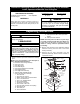
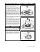
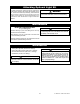
11.Use four #10-24 x 12mm pan head screws and
flat washers (supplied) to secure flange to blade
(Figure 6). Repeat for the remaining four blades.
Illustration may not show the exact flange you are
installing.
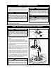
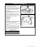
12.Use the 10 round recessed holes in the motor hub
marked with "5" and install the five blade
assemblies (ordered separately) in accordance
with Step 13.
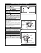
13.Attach one blade assembly to the motor hub
using two 10-32 x 5/8" oval head screws
(supplied) (Figure 7). Do not tighten completely at
this time. Install remaining blade assemblies in
the same way. Gently snug all flange screws to
the motor hub, working around the hub in a
clockwise sequence. Next, securely tighten all
flange screws, again working in a clockwise
sequence. Failure to follow this procedure could
result in fan wobble. This completes the blade
installation.
NOTE: Take care not to scratch fan housing when
installing blades.
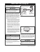
14. Position the switch cup cover onto the switch
cup, aligning the two holes. Use the two 8-32 x
3/8” pan head screws to secure cover (Figure 8).
NOTE: Make sure wires are not pinched between
switch cup and switch cup cover.
How to Put Your Ceiling Fan Together (continued)
BLADE
FLANGE
FAN BLADE
(Sold Separately)
FLAT WASHER (4)
#10-24 x 12mm PAN HEAD
BLADE SCREW (4)
Figure 6
10-32 x 5/8" OVAL HEAD SCREWS
(2 PER BLADE ASSEMBLY)
Figure 7
#8 - 32 x3/8" PAN
HEAD SCREW (2)
SWITCH CUP
COVER
SWITCH CUP
Figure 8