
Fan User Manual


9
Using Your Ceiling Fan
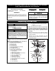
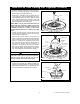
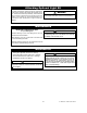
25-WATT (Max.) CANDELABRA
BASE LAMPS (3)
UPLIGHT
SOCKETS (3)
Figure 14
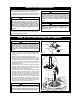
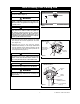
SPEED CONTROL
PULL CHAIN
ACCENT LIGHT
PULL CHAIN
PENDANT
COUPLING
REVERSE
SWITCH
LARGE
PENDANT
COUPLING
Figure 15
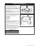
1. Screw three 25-watt (maximum) candelabra base
lamps (supplied) into the uplight sockets on top of
the fan housing assembly (Figure 14).
2. Slide the large pendant onto the the speed control
pull chain, secure by connecting the coupling to the
chain. Slide the pendant onto the accent light pull
chain, secure by connecting the coupling to the
chain. (Figure 15).
3. Assembly of the ceiling fan is now complete.
Restore electrical power to the branch circuit at the
fuse box or breaker panel.
4. When controlled by a wall switch, check the
operation of accent light by gently pulling on the
2-position accent light control pull chain. (This
switch has the shorter pull chain.) The speed
control operating sequence is as follows:
THREE-SPEED
1st Pull—HIGH
2nd Pull—Medium
3rd Pull—Low
4th Pull—OFF
5. When operated by an Emerson Remote Control,
check operation of fan and light in accordance with
the Remote Control Owner’s Manual.
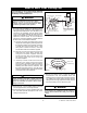
6. All fans are shipped from the factory with the
reversing switch positioned to circulate air
downward.
7. If airflow is desired in the opposite direction, turn
the fan off and wait for the blades to stop turning.
Then slide the reversing switch, located on switch
cup, to the opposite position (Figure 15) and turn
the fan on again. The blades will turn in the
opposite direction and reverse the airflow.
Reverse Switch Information
Season Rotation Direction Switch Position
Summer Counter-Clockwise Right
Winter Clockwise Left
U.L. Model No.: CF4801 and CF4501