READ AND SAVE THESE INSTRUCTIONS LOFT™ 60” Damp Location Ceiling Fan Owner's Manual Model Numbers CF765BQ01 - Barbeque Black CF765BS01 - Brushed Steel CF765WW01 - Appliance White Net Weight: 16.7 Lbs. Questions, problems, missing parts: Before returning to the store call Emerson Electric Customer Service 8 a.m. - 6 p.m., EST, Monday-Friday Part No. F40BP73780002 Revision: 130211 1-800-654-3545 www.emersonfans.com Form No. BP7378-2 U.L. Model No.
READ AND SAVE THESE INSTRUCTIONS Safety Instructions ! 3. The outlet box and joist must be securely mounted and capable of reliably supporting at least 50 pounds. Use only U.L. outlet boxes listed as “Acceptable for Fan Support of 22.7kg. (50 lbs.) or less”, and use the mounting screws provided with the outlet box. Most outlet boxes commonly used for support of light fixtures are not acceptable for fan support and may need to be replaced. Consult a qualified electrician if in doubt. 4.
Unpacking Instructions PACKAGE CONTENTS WARNING ! Do not install or use fan if any part is damaged or missing.
This Manual Is Designed to Make it as Easy as Possible for You to Assemble, Install, Operate and Maintain Your Ceiling Fan Installed Wire Length Up to 50 ft. 50-100 ft. Tools Needed for Assembly One Phillips head screwdriver One wire stripper One stepladder ! Materials Wire Size A.W.G. 14 12 WARNING Before assembling your ceiling fan, refer to section on proper method of wiring your fan (page 9).
Ceiling Fan Assembly CAUTION: The blade assemblies must be mounted on the motor assembly so that the raised lip edge is facing up (Figure 1). REVERSING SWITCH 1/4-20 x 12mm PAN HEAD SCREW 1/4" LOCKWASHER 1/4" FLAT WASHER 1. Rotate the motor hub so the notched area is above the screw hole in the motor hub. Install one blade assembly on the top of the motor assembly using two 1/4-20 x 12mm pan head screws, two 1/4” lockwashers and two 1/4” flat washers (supplied) (Figure 1).
Ceiling Fan Assembly (continued) 8. Make sure the grommet is properly installed in the coupling cover, then slide the coupling cover on the downrod until it rests on the motor housing. Place the ceiling cover over the downrod. Be sure that the ceiling cover and the coupling cover are both oriented correctly (Figure 5). CEILING COVER 9. Reinstall the hanger ball (Figure 6) on the downrod as follows. Route the two 80” motor leads through the hanger ball.
How to Hang Your Ceiling Fan ! CEILING WARNING The fan must be hung with at least 7' of clearance from floor to blades (Figure 7). ! AT LEAST 7' WARNING The outlet box and joist must be securely mounted and capable of supporting at least 50 lbs. Use only a U.L. outlet box listed as “Acceptable for Fan Support of 22.7kg. (50 lbs.) or less”. ! WARNING To reduce the risk of fire, electric shock, or personal injury, mount fan to outlet box marked “Acceptable for Fan Support of 22.7kg. (50 lbs.
How to Wire Your Ceiling Fan & Install the Control If you feel that you do not have enough electrical wiring knowledge or experience, have your fan installed by a licensed electrician. 1. Connect the green grounding lead from the hanger ball and the green grounding lead from the hanger bracket to the grounding conductor of supply (this may be a bare wire or wire with green colored insulation). Securely connect wires with wire connectors supplied. (Figure 10.
How to Wire Your Ceiling Fan & Install the Control (con’t.) General This control is designed to operate only one ceiling fan 6. Before disconnecting power, ensure that the fan is set at the highest speed. NOTE: Electric connections should be in accordance with the National Electrical Codes and all Local Codes. Before starting, disconnect power to the circuit at the fuse box or circuit breaker panel. SWITCH 7. Remove the faceplate and screws from the existing wall switch.
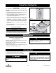
Using Your Ceiling Fan IMPORTANT Fan installation must be completed, including the installation of the fan blades, before testing of the controls. 1. Restore electrical power to the outlet box by turning the electricity on at the main fuse box. 2. Check the operation of the fan by sliding the bar of the control through the four positions marked 1 - 4 (“0” position is OFF) (Figure 15). 3. All fans are shipped from the factory with the reversing switch positioned to circulate air downward.
Energy Efficient Use of Ceiling Fans chill effect, making you "feel" cooler. Select a fan speed that provides a comfortable breeze, lower speeds consume less energy. In the winter, reverse the motor and operate the ceiling fan at low speed in the clockwise direction. This produces a gentle updraft, which forces warm air near the ceiling down into the occupied space.
Repair Parts 1 2 3 9 4 4 3 21 2 1 0 15 14 8 7 16 13 17 10 11 12 6 5 20 18 19 12 U.L. Model No.
Repair Parts Listing Model Numbers Key No.
Notes 14 U.L. Model No.
Emerson Air Comfort Ceiling Fan Limited Warranty What The Limited Warranty Covers: This limited warranty is offered by Air Comfort Products division of Emerson Electric Co. ("Emerson" "we" or "us") located at the address stated below to the original retail purchaser ("you" or "your") of an Emerson Air Comfort Ceiling Fan product ("Emerson Ceiling Fan") and covers the motor and the other components and accessories of the Emerson Ceiling Fan against all defects in workmanship and materials.
Air Comfort Products DIVISION OF EMERSON ELECTRIC CO. 8100 W. Florissant • St. Louis, MO 63136 Questions, problems, missing parts: Before returning to the store call Emerson Electric Customer Service 8 a.m. - 6 p.m., EST, Monday-Friday 1-800-654-3545 www.emersonfans.com Retain this manual for future use. Part No. F40BP73780002 Revision: 130211 Printed in China 02/13 Form No. BP7378-2 U.L. Model No.