READ AND SAVE THESE INSTRUCTIONS MONTEREY II™ 52” Ceiling Fan Owner's Manual Model Numbers CF772BS00 - Brushed Steel CF772ORB00 - Oil Rubbed Bronze CF772SW00 - Satin White Net Weight: 25.4 Lbs. Questions, problems, missing parts: Before returning to the store call Emerson Electric Customer Service 8 a.m. - 6 p.m., Eastern, Monday-Friday Part No. F40BP74670001 Revision: 131015 1-800-654-3545 www.emersonfans.com Form No. BP7467-1 E.T.L. Model No.
Table of Contents Section Page Section Safety Instructions . . . . . . . . . . . . . . . . . . . . . . . . . . . . . . . .2 1. Unpacking Instructions . . . . . . . . . . . . . . . . . . . . . . . . .3-4 2. Electrical Requirements . . . . . . . . . . . . . . . . . . . . . . . . . .4 3. Ceiling Fan Assembly . . . . . . . . . . . . . . . . . . . . . . . . . .5-7 4. Energy Efficient Use of Ceiling Fans . . . . . . . . . . . . . . . .7 5. How to Hang Your Ceiling Fan . . . . . . . . . . . . . . . . . . . .
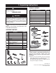
1. Unpacking Instructions PACKAGE CONTENTS WARNING ! Do not install or use fan if any part is damaged or missing.
1. Unpacking Instructions (continued) This Manual Is Designed to Make it as Easy as Possible for You to Assemble, Install, Operate and Maintain Your Ceiling Fan Wire Size A.W.G. 14 12 Installed Wire Length Up to 50 ft. 50-100 ft. Tools Needed for Assembly One Phillips head screwdriver One stepladder One 1/4” blade screwdriver One wire stripper One 5/16” open end wrench, or pliers Three wire connectors (supplied).
3. Ceiling Fan Assembly 1. Remove the hanger ball by loosening the setscrew in the hanger ball until the ball falls freely down the downrod (Figure 1). Remove the pin from the downrod, then remove the hanger ball. Retain the pin and hanger ball for reinstallation in Step 5. PIN HANGER BALL 2. Separate, untwist and unkink the three 80” motor leads. Route the motor lead wires through the downrod. Align the clevis pin holes in the downrod with the holes in the motor coupler.
3. Ceiling Fan Assembly (continued) 7. Mount blade flange to fan blade using three #10-32 x .25” slotted Phillips washers head screws (Figure 5). #10-32 x .25" SLOTTED PHILLIPS WASHER HEAD BLADE SCREW (3) 8. Repeat this procedure for the remaining four blades and flanges. ! WARNING BLADE FLANGE To reduce the risk of personal injury, do not bend the blade flange when installing the blade flanges, balancing the blades or cleaning the fan. Do not insert foreign objects in between rotating fan blades.
3. Ceiling Fan Assembly (continued) 15. Engage the connector of the switch housing assembly with the motor connector (Figure 8). The two connectors are keyed and color-coded and must be mated correctly (color-to-color) before they can be engaged. Make sure the connector latch closes properly. SWITCH HOUSING ASSEMBLY SWITCH HOUSING ASSEMBLY CONNECTOR 16. Position the switch housing assembly on the switch housing cover plate and align the holes in the switch housing assembly with the holes in the plate.
5. How to Hang Your Ceiling Fan ! CEILING WARNING The fan must be hung with at least 7' of clearance from floor to blades (Figure 10). ! WARNING AT LEAST 7' The outlet box and joist must be securely mounted and capable of supporting at least 50 lbs. Use only a U.L. outlet box listed as “Acceptable for Fan Support of 22.7kg. (50 lbs.) or less”. ! Figure 10 WARNING To reduce the risk of fire, electric shock, or personal injury, mount fan to outlet box marked “Acceptable for Fan Support of 22.7kg.
6. How to Wire Your Ceiling Fan If you feel that you do not have enough electrical wiring knowledge or experience, have your fan installed by a licensed electrician. 1. Connect the green grounding lead from the hanger ball and the green grounding lead from the hanger bracket to the grounding conductor of supply (this may be a bare wire or wire with green colored insulation). Securely connect wires with wire connectors supplied. (Figure 13.
7. Using Your Ceiling Fan 1. Restore electrical power to the outlet box by turning the electricity on at the main fuse box. 2. Check the operation of the fan by gently pulling on the pull chain switch. 3. All fans are shipped from the factory with the reversing switch positioned to the “left” circulate air downward. If airflow is desired in opposite direction, turn your fan OFF and wait for the blades to stop turning, then slide the reversing switch to the “right” position, and turn fan on again. 4.
10. Trouble Shooting ! WARNING: FOR YOUR OWN SAFETY TURN OFF POWER AT FUSE BOX OR CIRCUIT BREAKER BEFORE TROUBLE SHOOTING YOUR FAN. TROUBLE 1. Fan will not start. PROBABLE CAUSE SUGGESTED REMEDY 1. Fuse or circuit breaker blown. 1. Check main and branch circuit fuses or circuit breakers. 2. Loose power line connections to the fan, or loose switch wire connections in the switch housing. 2. Check line wire connections to fan and switch wire connections in the switch housing.
11. Repair Parts 2 1 3 5 17 4 16 6 7 18 9 8 12 20 19 14 21 22 10 23 11 13 15 12 E.T.L. Model No.
11. Repair Parts Listing Model Numbers Key No. Description CF772BS00 CF772ORB00 CF772SW00 761655-17 761655-32 761655-92 1 2 3 Hanger Ball Assembly, Consisting of: Hanger Bracket Hanger Ball Downrod, 4.5” — — — — — — — — — * 4 5 6 7 8 9 10 11 12 13 14 15 16 Parts Bag Containing: Wire Connector (3) Threaded Stud (2) Lockwasher (2) Knurled Knob (2) Pin, Clevis Clip, Hairpin Wood Ball/Chain Screw, 1/4-20 x .5” (11) Screw, #10-32 x .
Notes 14 E.T.L. Model No.
Emerson Air Comfort Ceiling Fan Limited Warranty What The Limited Warranty Covers: This limited warranty is offered by Air Comfort Products division of Emerson Electric Co. ("Emerson" "we" or "us") located at the address stated below to the original retail purchaser ("you" or "your") of an Emerson Air Comfort Ceiling Fan product ("Emerson Ceiling Fan") and covers the motor and the other components and accessories of the Emerson Ceiling Fan against all defects in workmanship and materials.
Air Comfort Products DIVISION OF EMERSON ELECTRIC CO. 8100 W. Florissant • St. Louis, MO 63136 Questions, problems, missing parts: Before returning to the store call Emerson Electric Customer Service 8 a.m. - 6 p.m., Eastern, Monday-Friday 1-800-654-3545 www.emersonfans.com Retain this manual for future use. Part No. F40BP74670001 Revision: 131015 Printed in China 10/13 Form No. BP7467-1 E.T.L. Model No.