READ AND SAVE THESE INSTRUCTIONS MONTEREY LUMINA™ 52” Ceiling Fan Owner's Manual Model Numbers CF776BS00 - Brushed Steel CF776ORB00 - Oil Rubbed Bronze CF776SW00 - Satin White Net Weight: 28.9 Lbs. Questions, problems, missing parts: Before returning to the store call Emerson Electric Customer Service 8 a.m. - 6 p.m., EST, Monday-Friday Part No. F40BP74680000 11/12 1-800-654-3545 www.emersonfans.com Form No. BP7468 U.L. Model No.
READ AND SAVE THESE INSTRUCTIONS Safety Instructions ! 3. The outlet box and joist must be securely mounted and capable of reliably supporting at least 50 pounds. Use only U.L. outlet boxes listed as “Acceptable for Fan Support of 15.9kg. (35 lbs.) or less”, and use the mounting screws provided with the outlet box. Most outlet boxes commonly used for support of light fixtures are not acceptable for fan support and may need to be replaced. Consult a qualified electrician if in doubt. 4.
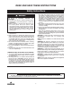
Unpacking Instructions ! PACKAGE CONTENTS WARNING Do not install or use fan if any part is damaged or missing. Call Toll-Free: Part A 1-800-654-3545 B C Ceiling Canopy Coupler Cover 1 1 D E F G Blade Flanges Fan Blades Hanger Bracket Hanger Ball/Downrod Assembly 5 5 1 1 H I J K Switch Housing Assembly Switch Housing Cover Plate Light Fitter Assembly Glass Bowl 1 1 1 1 L 60-Watt (max.
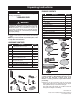
This Manual Is Designed to Make it as Easy as Possible for You to Assemble, Install, Operate and Maintain Your Ceiling Fan Installed Wire Length Up to 50 ft. 50-100 ft. Tools Needed for Assembly One Phillips head screwdriver One stepladder One 1/4” blade screwdriver One wire stripper One 5/16” open end wrench, or pliers Three wire connectors (supplied). Wire Size A.W.G. 14 12 WARNING ! Before assembly your ceiling fan, refer to section on proper method of wiring your fan (page 10).
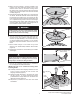
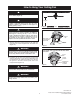
4. Make sure the grommet is properly installed in the coupler cover, then slide the coupler cover on the downrod until it rests on the motor housing. Place the ceiling cover over the downrod. Be sure that the ceiling cover and the coupler cover are both oriented correctly (Figure 3). CEILING COVER 5. Reinstall the hanger ball (Figure 4) on the downrod as follows. Route the three 80” motor leads through the hanger ball.
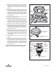
13. Remove one of the screws from the switch adapter. Retain for future installation. Loosen the two remaining screws in the switch adapter for installation of the switch housing cover plate (Figure 7). REMOVE MOTOR HOUSING SCREW 14. Place the switch housing cover plate onto the switch adapter. Engage the keyholes of the switch housing cover plate by rotating the switch housing cover plate clockwise on the switch adapter. Retighten the two screws and reinstall the screw previously removed.
20. Install three 60-watt (maximum) candelabra base light bulbs (included) into the light fitter sockets (Figure 11). ! SWITCH HOUSING/ LIGHT KIT FITTER ASSEMBLY WARNING SWITCH HOUSING ASSEMBLY CONNECTOR Over lamping the fan will result in the light bulbs being automatically shut off. Use only 60-watt maximum candelabra light bulbs. Turn off the electricity before replacing the light bulbs. MOTOR HOUSING CONNECTOR 21. Remove the finial nut and outer bowl cap from the light fitter (Figure 12). 22.
Electrical Requirements Your new ceiling fan will require a grounded electrical supply line of 120 volts AC, 60 Hz, 15 amp circuit. ! The outlet box must be securely anchored and capable of withstanding a load of at least 50 pounds. If your fan is to replace an existing ceiling light fixture, turn electricity off at the main fuse box at this time and remove the existing light fixture.
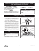
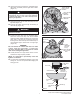
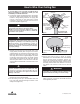
How to Hang Your Ceiling Fan ! CEILING WARNING The fan must be hung with at least 7' of clearance from floor to blades (Figure 13). ! WARNING AT LEAST 7' The outlet box and joist must be securely mounted and capable of supporting at least 50 lbs. Use only a U.L. outlet box listed as “Acceptable for Fan Support of 15.9kg. (35 lbs.) or less”. ! Figure 13 WARNING To reduce the risk of fire, electric shock, or personal injury, mount fan to outlet box marked “Acceptable for Fan Support of 15.9kg.
How to Wire Your Ceiling Fan If you feel that you do not have enough electrical wiring knowledge or experience, have your fan installed by a licensed electrician. 1. Connect the green grounding lead from the hanger ball and the green grounding lead from the hanger bracket to the grounding conductor of supply (this may be a bare wire or wire with green colored insulation). Securely connect wires with wire connectors supplied. (Figure 16.
Using Your Ceiling Fan 1. Restore electrical power to the outlet box by turning the electricity on at the main fuse box. 2. Check the operation of the fan by gently pulling on the pull chain switch. 3. All fans are shipped from the factory with the reversing switch positioned to the “left” circulate air downward. If airflow is desired in opposite direction, turn your fan OFF and wait for the blades to stop turning, then slide the reversing switch to the “right” position, and turn fan on again. 4.
Repair Parts 2 1 3 5 15 4 6 7 16 9 8 22 23 12 18 17 20 19 24 21 11 13 25 10 10 12 U.L. Model No.
Repair Parts Listing Model Numbers Key No. Description CF776BS00 CF776ORB00 CF776SW00 760750-17 760750-32 760750-92 1 2 3 Hanger Ball Assembly, Consisting of: Hanger Bracket Hanger Ball Downrod, 4.5” — — — — — — — — — * 4 5 6 7 8 9 10 11 12 13 14 Parts Bag Containing: Wire Connector (3) Threaded Stud (2) Lockwasher (2) Knurled Knob (2) Pin, Clevis Clip, Hairpin Wood Ball/Chain Screw, 1/4-20 x .5” (1) Screw, #10-32 x .25” (16) Screw.
Trouble Shooting ! WARNING: FOR YOUR OWN SAFETY TURN OFF POWER AT FUSE BOX OR CIRCUIT BREAKER BEFORE TROUBLE SHOOTING YOUR FAN. TROUBLE 1. Fan will not start. PROBABLE CAUSE SUGGESTED REMEDY 1. Fuse or circuit breaker blown. 1. Check main and branch circuit fuses or circuit breakers. 2. Loose power line connections to the fan, or loose switch wire connections in the switch housing. 2. Check line wire connections to fan and switch wire connections in the switch housing.
Emerson Air Comfort Ceiling Fan Limited Warranty What The Limited Warranty Covers: This limited warranty is offered by Air Comfort Products division of Emerson Electric Co. ("Emerson" "we" or "us") located at the address stated below to the original retail purchaser ("you" or "your") of an Emerson Air Comfort Ceiling Fan product ("Emerson Ceiling Fan") and covers the motor and the other components and accessories of the Emerson Ceiling Fan against all defects in workmanship and materials.
Air Comfort Products DIVISION OF EMERSON ELECTRIC CO. 8100 W. Florissant • St. Louis, MO 63136 Questions, problems, missing parts: Before returning to the store call Emerson Electric Customer Service 8 a.m. - 6 p.m., EST, Monday-Friday 1-800-654-3545 www.emersonfans.com Retain this manual for future use. Part No. F40BP74680000 11/12 Form No. BP7468 U.L. Model No.