
user manual


PMC Hardware Preparation and Installation
MVME7100 Single Board Computer Installation and Use (6806800E08A)
41
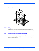
Installation and Removal Procedure
To begin the installation of the transition module in a chassis, proceed as follows:
1. Turn all equipment power OFF and disconnect the power cable from the AC power
source.
2. Remove the chassis cover as instructed in the equipment user's manual.
3. Remove the filler panel(s) from the appropriate card slot(s) at the rear of the chassis
(if the chassis has a rear card cage).
4. Install the top and bottom edge of the transition module into the rear guides of the
chassis.
5. Ensure that the levers of the two injector/ejectors are in the outward position.
6. Slide the transition module into the chassis until resistance is felt.
7. Simultaneously move the injector/ejector levers in an inward direction.
8. Verify that the transition module is properly seated and secure it to the chassis using
the two screws located adjacent to the injector/ejector levers.
9. Connect the appropriate cables to the transition module.
To remove the transition module from the chassis, reverse the procedure and press the red
locking tabs (IEEE handles only) to extract the board.
2.5.2 PMC
The PMC connectors are placed to support two single-width PMCs or one double-width PMC.
PMC site 1 supports front PMC I/O and rear PMC I/O via the Jn4 connector. PMC 1 I/O is routed
to the VME P2 connector. PMC site 2 only supports front PMC I/O and does not have a Jn4
connector. The PMC 1 Jn4 user I/O signals only support low-current high-speed signals and
thus do not support current-bearing power supply usage.
In most cases, the PMCs are already in place on the baseboard. The user-configured switches
are accessible with the PMCs installed. The onboard PMC sites are configured to support +3.3
V I/O PMC modules. The onboard PMC sites do not support +5.0 V I/O PMC modules.
Follow these steps to install a PMC onto the MVME7100 board.