
user manual


MVME7100 Single Board Computer Installation and Use (6806800E08A)
Controls, LEDs, and Connectors Connectors
60
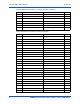
3.3.3.4 Serial Port Connector (COM1/J1)
There is one front access asynchronous serial port interface (SP0) that is routed to the
mini DB-9 front-panel connector. The pin assignments for these connectors are as follows:
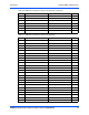
3.3.3.5 VMEbus P1 Connector
The VME P1 connector is a 160-pin DIN. The P1 connector provides power and VME signals
for 24-bit address and 16-bit data. The pin assignments for the P1 connector is as follows:
51 GND AD36 52
53 AD35 AD34 54
55 AD33 GND 56
57 +3.3V (VIO) AD32 58
59 Reserved Reserved 60
61 Reserved GND 62
63 GND Reserved 64
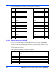
Table 3-11 PMC Slot 2 Connector (J23) Pin Assignments (continued)
Pin Signal Signal Pin
Table 3-12 COM1 Port Connector Pin Assignments
Pin Signal
1 No connect
2RX
3TX
4 No Connect
5GND
6 No Connect
7RTS
8CTS
9 No Connect
Table 3-13 VMEbus P1 Connector Pin Assignments
ROW Z ROW A ROW B ROW C ROW D
1 Reserved D00 BBSY* D08 +5V 1
2 GND D01 BCLR* D09 GND 2
3 Reserved D02 ACFAIL* D10 Reserved 3
4 GND D03 BG0IN* D11 Reserved 4
5 Reserved D04 BG0OUT* D12 Reserved 5
6 GND D05 BG1IN* D13 Reserved 6