
user manual


MVME7100 Single Board Computer Installation and Use (6806800E08A)
Transition Module Features
76
5.3 Features
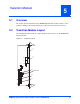
The MVME7216E transition module is for I/O routing through the rear of a compact VMEbus
chassis. It connects directly to the VME backplane in chassis’ with an 80 mm deep rear
transition area. The MVME7216E is designed for use with the host MVME7100 board. It has
these features:
5.4 SEEPROM Address Switch, S1
A 4-position SMT configuration switch is located on the MVME7216E transition module to set
the device address of the RTM serial EEPROM device. The switch settings are defined in the
next table. To see switch location, refer to Figure 5-1 on page 75.
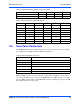
Table 5-1 Transition Module Features
Function Features
I/O One five-row P2 backplane connector for serial and Ethernet I/O passed from the SBC
Four RJ-45 connectors for rear panel I/O: four asynchronous serial channels
Two RJ-45 connectors with integrated LEDs for rear panel I/O: two 10/100/1000
Ethernet channels
One PIM site with rear panel I/O
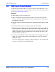
Figure 5-2 Block Diagram
PIM
PMC 1 Jn4 IO
Serial Port 1
GigE 1
PIM IO
GigE
RJ-45
Serial
RJ-45
Serial
RJ-45
Serial
RJ-45
Serial
RJ-45
GigE
RJ-45
Rear Panel
Serial Port 2
Serial Port 3
Serial Port 4
GigE 2
P2
I2C Bus
VPD
8 KB
Figure 5-3 S1 Switch Positions
ON
1
2
34