Instruction Manual Document: CI-CW-GFC-ISTRAN Part: D301647X012 November, 2009 ControlWave GFC IStran ControlWave GFC IStran Intrinsically Safe Communication Interface Remote Automation Solutions www.EmersonProcess.
IMPORTANT! READ INSTRUCTIONS BEFORE STARTING! Be sure that these instructions are carefully read and understood before any operation is attempted. Improper use of this device in some applications may result in damage or injury. The user is urged to keep this book filed in a convenient location for future reference. These instructions may not cover all details or variations in equipment or cover every possible situation to be met in connection with installation, operation or maintenance.
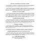
Emerson Process Management Training GET THE MOST FROM YOUR EMERSON INSTRUMENT OR SYSTEM Avoid Delays and problems in getting your system on-line Minimize installation, start-up and maintenance costs. Make the most effective use of our hardware and software. Know your system. As you know, a well-trained staff is essential to your operation. Emerson offers a full schedule of classes conducted by full-time, professional instructors.
BLANK PAGE
ControlWave GFC-IStran Instruction Manual Contents Chapter 1 – Introduction 1.1 1-1 Physical Description..................................................................................................................1-2 1.1.1 IStran PCB ....................................................................................................................1-3 Chapter 2 – Function and Electrical Characteristics 2.1 2.2 2.3 Hazardous and Non-Hazardous Characteristics.......................................
ControlWave GFC-IStran Instruction Manual vi Contents Issued Nov-09
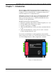
ControlWave GFC IS Communication Interface Manual (CI-CW-GFC-ISTRAN) Chapter 1 – Introduction The ControlWave GFC Intrinsically Safe IStran Communication Interface (IStran) allows an intrinsically safe ControlWave Gas Flow Computer / Corrector (CW-GFC-IS) to communicate with a device located in a Division 2 or non-hazardous area.
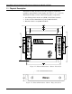
ControlWave GFC IS Communication Interface Manual (CI-CW-GFC-ISTRAN) 1.1 Physical Description The IStran assembly measures 6.25 inches (length) by 4.50 inches (width) by approximately 1 inch (depth). (See Figure 1-2, 1-3, and 1-4.) The IStran assembly consists of the following major components: One IStran printed circuit board (PCB) for the IStran assembly Yellow alodined aluminum base plate (0.060 inch thick) Black anodized cover (0.090 inch thick) Figure 1-2.
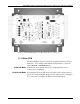
ControlWave GFC IS Communication Interface Manual (CI-CW-GFC-ISTRAN) Figure 1-4. IStran PCB Mounted on Base Plate (Cover removed) 1.1.1 IStran PCB The IStran PCB provides two interfaces designated hazardous and nonhazardous. You configure each interface independently to operate in either switched or unswitched mode. Switched Mode Switched mode sets the TX drivers into a high-impedance state to reduce power consumption.
ControlWave GFC IS Communication Interface Manual (CI-CW-GFC-ISTRAN) 1-4 Introduction Issued Nov-09
ControlWave GFC IS Communication Interface Manual (CI-CW-GFC-ISTRAN) Chapter 2 – Function and Electrical Characteristics You can use the ControlWave GFC Intrinsically Safe IStran Communication Interface (IStran) in both hazardous and nonhazardous environments. 2.1 Hazardous and Non-Hazardous Characteristics Table 2-1 provides the characteristics common to both the hazardous and non-hazardous IStran interfaces: Table 2-1.
ControlWave GFC IS Communication Interface Manual (CI-CW-GFC-ISTRAN) Position Name Function HPOUT and signals) HJ1-7 HPOUT Hazardous Power HJ1-6 HRX3 Signal Input HJ1-5 HRX2 Signal Input HJ1-4 HJ1-3 HJ1-2 HJ1-1 HJP1-1 HJP1-2 HJP1-3 HRX1 HTX3 HTX2 HTX1 SW COM UNSW Signal Input Signal Output (Follows NRX3) Signal Output (Follows NRX2) Signal Output (Follows NRX1) Jumper to COM for Switched Mode Mode Selection Common Jumper to COM for Unswitched Mode Table 2-3 provides the characteristics of the
ControlWave GFC IS Communication Interface Manual (CI-CW-GFC-ISTRAN) Figure 2-1. Setting Jumper HJP1 2.1.2 Non-Hazardous Interface Typically you connect the non-hazardous interface to a radio or modem located with the IStran assembly in a non-hazardous or Division 2 rated area. Table 2-4 identifies each connector position and the corresponding signal name, and provides a brief description of each I/O point on the non-hazardous interface. Table 2-4.
ControlWave GFC IS Communication Interface Manual (CI-CW-GFC-ISTRAN) Table 2-5 provides the characteristics of the non-hazardous interface. Table 2-5. Non-Hazardous Interface Characteristics Description 2-4 Specification NPIN Voltage (When HPOUT is not used) Minimum: Maximum: 5.
ControlWave GFC IS Communication Interface Manual (CI-CW-GFC-ISTRAN) Figure 2-2. Setting Jumper NJP1 2.2 Switched & Unswitched Modes You can configure each IStran interface independently to operate in switched or unswitched mode. In switched mode, the TX drivers can enter a high-impedance state to reduce power consumption. The outputs transition smoothly to and from the high-impedance state. Most modern device inputs pull the high impedance IStran output to ground and interpret it as a low, or mark state.
ControlWave GFC IS Communication Interface Manual (CI-CW-GFC-ISTRAN) 2.2.1 Configuring the Hazardous Interface for Switched Mode To configure the hazardous interface for switched mode, place the supplied shorting jumper in the HJP1 position marked SW (short HJP1 pins 1 and 2 as shown in Figure 2-1). If you don’t install a jumper at HJP1 the hazardous interface defaults to switched mode.
ControlWave GFC IS Communication Interface Manual (CI-CW-GFC-ISTRAN) When hazardous interface signal input HRX3 is at a high (positive) level, NPOUT turns on and can supply power to an external device. When HRX3 is at a low (or negative) level, NPOUT turns off. You determine the voltage drop between NPIN and NPOUT by multiplying the NPOUT load current by the NPIN to NPOUT on-resistance.
ControlWave GFC IS Communication Interface Manual (CI-CW-GFC-ISTRAN) 2-8 Function and Electrical Characteristics Issued Nov-09
ControlWave GFC IS Communication Interface Manual (CI-CW-GFC-ISTRAN) Chapter 3 – System Wiring This chapter includes details on grounding and wiring for the IStran. 3.1 Introduction to System Wiring The IStran connects a radio, modem, or other communications device to a ControlWave GFC-IS Flow Computer/Corrector.
ControlWave GFC IS Communication Interface Manual (CI-CW-GFC-ISTRAN) 3.3 Cable Length Underwriter’s Laboratories (UL) lists the IStran for use with cable lengths up to 25 feet on either or both interfaces. Typically, you install the IStran in close proximity to the communications device (connected to the non-hazardous interface) and at some distance from the CWGFC-IS (connected to the hazardous interface).
ControlWave GFC IS Communication Interface Manual (CI-CW-GFC-ISTRAN) Figure 3-2 is similar to Figure 3-1 except it uses an MDS radio instead of a modem. Figure 3-2. Radio System with Single Power Source Figures 3-3 and 3-4 illustrate an externally powered CW-GFC-IS (without a modem or radio). In this example, the external power source to the non-hazardous interface must not generate more than 16Vdc and must be able to supply at least 8Vdc.
ControlWave GFC IS Communication Interface Manual (CI-CW-GFC-ISTRAN) Figure 3-4.
ControlWave GFC IS Communication Interface Manual (CI-CW-GFC-ISTRAN) Chapter 4 – Installation 4.1 Installation Overview The IStran and the communications device reside in a non-hazardous or Division 2 rated area, while the CW-GFC-IS resides in a Division 1, Division 2, or non-hazardous area. You must provide a suitable enclosure for the IStran.
ControlWave GFC IS Communication Interface Manual (CI-CW-GFC-ISTRAN) IStran. Do not install any other wiring through the same hole or allow other wires to share a cable or conduit with the intrinsically safe wiring.
ControlWave GFC IS Communication Interface Manual (CI-CW-GFC-ISTRAN) Chapter 5 – Specifications 5.1 Environment The IStran design supports operation inside a building or a weatherproof enclosure only. 5.2 Operating Specifications Table 5-1 provides the operating specifications for the IStran: Table 5-1.
ControlWave GFC IS Communication Interface Manual (CI-CW-GFC-ISTRAN) 5-2 Specifications Issued Nov-09
WARRANTY A. Remote Automation Solutions (RAS) warrants that goods described herein and manufactured by RAS are free from defects in material and workmanship for one year from the date of shipment unless otherwise agreed to by RAS in writing. B. RAS warrants that goods repaired by it pursuant to the warranty are free from defects in material and workmanship for a period to the end of the original warranty or ninety (90) days from the date of delivery of repaired goods, whichever is longer. C.
How to return material for Repair or Exchange Before a product can be returned to Remote Automation Solutions (RAS) for repair, upgrade, exchange, or to verify proper operation, Form (GBU 13.01) must be completed in order to obtain a RA (Return Authorization) number and thus ensure an optimal lead time. Completing the form is very important since the information permits the RAS Watertown Repair Dept. to effectively and efficiently process the repair order. You can easily obtain a RA number by: A.
Remote Automation Solutions Repair Authorization Form (Providing this information will permit Remote Automation Solutions to effectively and efficiently process your return. Completion is required to receive optimal lead time. Lack of information may result in increased lead times.) Date ____________ RA # _________________ Standard Repair Practice is as follows: Variations to this is practice may be requested in the “Special Requests” section.
BLANK PAGE
ControlWave GFC-IStran Instruction Manual Index Non-Hazardous power output............................. 2-6 F Field wiring diagrams.......................................... 3-2 Figures 1-1. Istran Front View ..................................... 1-1 1-2. Physical Dimensions - Istran Front View 1-2 1-3. Physical Dimensions – IStran Edge (Side) View.............................................................. 1-2 1-4. Istran PCB Mounted on Base Plate ........ 1-3 2-1. Setting Jumper HJP1 ..................
Customer Instruction Manual CI-CW-GFC-ISTRAN November, 2009 ControlWave GFC IStran NOTICE Emerson Process Management Remote Automation Solutions 1100 Buckingham Street Watertown, CT 06795 Phone: +1 (860) 945-2262 Fax: +1 (860) 945-2525 www.EmersonProcess.com/Remote Emerson Process Management Remote Automation Solutions 6338 Viscount Rd. Mississauga, Ont. L4V 1H3 Canada Phone: 905-362-0880 Fax: 905-362-0882 www.EmersonProcess.com/Remote Emerson Process Management SA de CV Calle 10 #145 Col.