
Product data


June 2012
CWGFC
2 www.EmersonProcess.com/Remote
Item Descriptions and Specifications
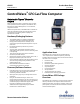
Standard equipment includes Lexan housing with 2-line
LCD, single board electronics assembly, and the standard
API 21.1 flow measurement application program. Standard
I/O count is 2 DI/PI (Pulse Inputs). Also included in the base
product are interfaces to Emerson’s gauge pressure or
multivariable, DP/P sensor assembly, an RTD interface, AUX
power output (e.g. to switch power to a radio), and shunt
regulator for solar panel charging of an internal lead acid cell
battery.
You can also specify all of the following:
Integral gauge pressure or multivariable (MVT) DP/P
sensor assembly, and upper range limits
Bendable RTD assembly, pre-wired
Thermowell
A two-line LCD with no pushbuttons, two-line LCD with
two pushbuttons, or a four-line LCD with 25-key keypad
I/O card, including 2 DI/DO, 4 DI, 2 DO and 2 HSC/DI
and, optionally, an additional 3 AI, 1 AO
Hazardous area approval — Class I, Division 2
Choice of integral, battery, and solar power systems
Choice of standard model modem or radio that is
installed on an internal bracket. Standard radios are
those that are commonly available from Freewave and
MDS.
Polyphaser surge suppressor for the radio
Performance
Computation Accuracy: 0.01% Corrected Flow,
including all input values
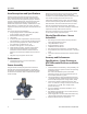
Sensor Assembly
Using the sensor assembly integrated in the instrument
package is the easiest implementation for a single meter
run; however, the standard application program also allows
use of external transmitters with or without the integrated
sensor assembly.
DP/P Multivariable (MVT) Sensor Assembly
Most two-run systems use the integrated sensor assembly
for the first run and an external, smart multivariable
transmitter, such as the 3808 MVT (which includes the exact
same sensor assembly), for the second meter run.
If the sensor assembly requires a repair, you can change it
out and continue operating with the electronics, including
flow information, alarms and historical archives, all intact.
Emerson recommends that you practice “depot level”
service. In other words, the sensor assembly is removed and
replaced at the shop rather than out at the site.
Each sensor assembly has a nine-digit part number, which
can be used to specify a replacement part.
Physical Specifications — Sensor
Assemblies
MVT Flange and Center Section and Gauge Pressure
Sensor Housing Material: 316 SS
Flange Bolt Material: 316 SS
Diaphragm Material: 316 SS
Fill Medium: DC 200 Silicone
MVT Flange Process Connections: ¼-inch NPT female
Gauge Pressure Sensor Process Connection: ½-inch NPT
male
Connects to the Processor Board via a dedicated SPI bus
cable
Accuracy and Performance
Specifications — Gauge Pressure or
MVT Differential Pressure and Static
Pressure
Combined effects of nonlinearity, nonrepeatability, and
hysteresis at reference pressure and over the operating
temperature range.
DP: ±0.075% of calibrated span or 0.02% of URL,
whichever is greater; SP: 0.075% of calibrated span or
0.02% of URL, whichever is greater.
Temperature Effect on Static and Differential Pressure:
±0.21% URL maximum combined shift of zero and span
with an ambient temperature change of 60ºC (108ºF)
Static Pressure Effects on Differential Pressure: Zero
Error: ±0.1% URL, for a change in static pressure of 1000
psi; Span error: ±0.1% URL, for a change in static
pressure of 1000 psi
Long Term Stability at Constant Conditions: ±0.1%
URL/Year maximum
MVT Mounting Position Effect: ±2-inch H
2
O maximum,
which can be calibrated out.
Power Supply Effect: ±0.005% of URL maximum for any
change within input power supply voltage range
Ripple and Noise: Per ISA 50.1 section 4.6