
Product data


CWGFC June 2012
www.EmersonProcess.com/Remote 3
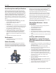
MVT Assembly Static Pressure
Orientation
For a multivariable sensor assembly, you can specify
whether the static pressure sensor is oriented to the right or
to the left from the point-of-view of a user looking at the
front of the ControlWave GFC. Following the AGA3-1992
convention, we refer to the static pressure sensor location
as the “upstream” (a.k.a. “high side”) location.
Integral Enclosure and LCD/Keypad
The standard LCD provides two lines and operates in a
continuous cycle mode. One of two optional configurations
can be selected instead: 4-line x 20-character LCD with
either a 2-button or 25-button keypad. Both display/keypad
assemblies have the same “footprint” on the front door.
Features — Display/Keypads
4-line by 20-character backlit liquid crystal display
Adjustable display contrast
Membrane keys with tactile feedback
Self-adhesive overlay mounts to the enclosure door or
panel (ControlWave GFC package is delivered with this
assembly installed on the door)
Easy configuration via ACCOL III Function Block
Scrolling display mode
Adjustable timer turns off display when not in use
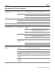
Specifications — Display/Keypads
Window size: 1.1 inches H x 3.1inches W (2.8 cm H x
7.9 cm W)
Character size: 4 mm H x 3 mm W
Dimensions: 7.4 inches H x 5.5 inches W (18.8 cm H x
14.0 cm W)
Power consumption: 2.5 mA @ 3.3 V (0.008 watts)
Operating Temperature: -4 to 158ºF (-20 to 70ºC)
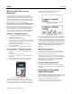
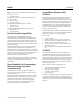
LCD Panel with 25-button keypad
The 2-button display allows an operator to view site,
configuration, and process data. The screens are organized
in a series of lists. The operator can select a list and then
manually scroll through the data. Additionally, a “scroll list”
can be defined. The ControlWave GFC can be set to
automatically sequence through this list.
2-button display example
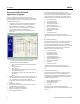
25-button display example
The 25-button display/keypad performs the same functions
and additionally allows the operator to view and modify
ControlWave GFC inputs, process variables, calculated
variables, setpoints, tuning parameters, and outputs used in
a measurement or control application. Status bits include
the alarm state, alarm acknowledge, control, and manual
(Auto/Man). Providing access to such variable information
allows you to have complete control over the process
operation.
Mounting Hardware
You can specify optional hardware for pole-mounting or
wall-mounting. The “pole-mount” kit includes two wall-
mounting plates and two pipe clamps.
Without the mounting hardware, the ControlWave GFC is
suitable for process-mounting to a direct-mount manifold.
Note that this is appropriate only for models with MVT
sensor assemblies. A unit with a gauge pressure sensor
should not be process-mounted.
Processor/Main Electronics
The processor electronics assembly consists of a single
circuit board, which is installed on the far left-hand side in
the enclosure.
ControlWave GFC Standard
Application Program
The ControlWave GFC comes preloaded with the 1 — 2 run
M&R load application. ControlWave GFC is shipped with the
program (.profile) loaded in Flash and the Flash
Configuration Program (FCP) also loaded.
You interface to the Standard Application Program via a
series of straight-forward web-style menu pages.