Copeland Scroll® Compressor Module Installation, Operation & Maintenance Manual Model Family SZV32 SZV44 SZO44 SZO56
Dual-Compressor Module TABLE OF CONTENTS TABLE OF CONTENTS Compressor Module Nomenclature. ............................................................................................ iv Important Safety Information........................................................................................................1 1.0 Introduction.......................................................................................................................3 1.1 The Compressor Module........................
Dual-Compressor Module TABLE OF CONTENTS 4.2 Maintenance Tools....................................................................................................................... 20 4.3 Checking the Oil Level................................................................................................................. 21 4.3.1 Oil Level Guidelines - Minimum Speed..........................................................................................21 4.3.
Dual-Compressor Module TABLE OF CONTENTS FIGURES Figure 1 Compressor Module Components .........................................................................................................3 Figure 2 Copeland Scroll® Compressor Cross Section.........................................................................................4 Figure 3 Typical Compressor Package ................................................................................................................
Dual-Compressor Module Compressor Module Nomenclature Compressor Module Nomenclature Model Max Delivery Pressure (PSIG) Max Flow (MCFD) Drive HP High Press Switch Setting (PSIG) Low Press Switch Setting High Temp Setting °F (°C) Oil Thermal Bypass Valve Setpoint °F (°C) Gas Bypass Valve Module Weight (Lbs.) Dual Scroll Units SZO56C1A-EDE-110 150 260 30 215 0.75 PSIG (52 mbarg) 240 (116) 200 NO 625 SZO44C1A-EDE-140 190 200 30 215 0.
Dual-Compressor Module Important Safety Information Important Safety Information This manual contains important instructions for installation, operation and maintenance of your Copeland Scroll® Compressor Module. WARNING The Compressor Module must be installed ONLY in systems that have been designed by qualified engineering personnel. The system must conform to all applicable local and national regulations and safety standards.
Dual-Compressor Module Important Safety Information Safety Symbols Used in This Manual SAFETY ALERT SYMBOL When you see this symbol on the Compressor Module or in this manual, look for one of the following words and be aware of the potential for personal injury or property damage. WARNING A Warning describes hazards that CAN or WILL cause serious personal injury, death or major property damage. CAUTION A Caution describes hazards that CAN cause personal injury or property damage.
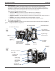
Dual-Compressor Module Introduction 1.0 Introduction The Copeland Scroll® SZO44 Compressor Module comes equipped with two Copeland Scroll® Compressors designed for Class I, Division II applications. The Compressor Module is designed for assembly into a Compressor Package ready for service in the field; the completed housing is done by equipment Packagers. This section provides an overview of these components.
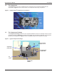
Dual-Compressor Module 1.2 Introduction The Compressor The Compressor refers to the Copeland Scroll® Compressor. Each Compressor Module has two Compressors. Figure 2 shows a cross-section of a Compressor and its key components. Figure 2 1.3 Copeland Scroll® Compressor Cross Section The Compressor Package The Compressor Package consists of the Compressor Module housed in an assembly ready for service in the field.
Dual-Compressor Module Installation 2.0 Installation 2.1 Installation Guidelines 2.1.1 Required Component—Inlet Gas Scrubber An appropriate inlet gas scrubber is REQUIRED to remove liquids from the gas prior to compression. If there is potential for liquid slugging, a suitable trap must be installed to prevent liquid from flooding and damaging the Compressor.
Dual-Compressor Module Installation NOTE: Required Component – High Pressure Discharge Gas Bypass Valve In response to customer requests to eliminate redundancy, the high pressure discharge gas bypass (recycle) valve was removed from some of the scroll modules (see table below).
Dual-Compressor Module 2.4 Installation Installation Clearance and Dimensions Allow sufficient clearance on all sides for service access, especially for gas and electrical connections at the rear of the Compressor Module. Check applicable national and local electrical codes. Cooling air flow is back to front—from the gas connection end to the oil cooler end. Do not block or restrict the cooler fans or oil cooler. Refer to Figure 4 for the dimensions of the Compressor Module.
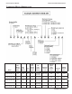
Dual-Compressor Module 2.5 Installation Process and Instrumentation Diagrams (P&IDs) Figure 5 Compressor Module Gas and Oil Flow Diagram and Safety Shutdowns PSLL 001 Gas Discharge 1" -NPT BPV-01 PS 001 PI 002 Gas Suction 1-1/2" -NPT C-01 PS 002 PSHH 002 TS 002 TSHH 002 TE 002 PI 003 SEP-02 480V J.B.
Dual-Compressor Module 2.6 Electrical Controls 2.6.1 General Considerations Installation All shutdown devices are dry contact switches rated Class I, Division II that are wired to a terminal box for connection to the packager supplied control circuit. The common wires on all switches are connected together. All switches are closed unless a fault condition is detected. All safety and protective devices must be installed and used in accordance with applicable codes and regulations.
Dual-Compressor Module 2.6.2 Installation Oil Cooler Fan Control The Compressor Module temperature is controlled by managing module oil flow and temperature. The module’s precise temperature control is critical to system performance and equipment life. Maintaining proper temperature control also reduces the possibility of gas condensing into liquids during operation. • Cooling fans require 24VDC, 4.5A (105 Watts) x 2 (9A 210W total) for the Compressor Module.
Dual-Compressor Module Figure 8 Installation Optional Customer-Installed High Temperature Fan Control System SZO44 Compressor Module Power Supply 24VDC PLC Or Temperature Control • • • • • Figure 9 0-10VDC Fan Speed Signal 0.9V = Off; 1.3V = 50%; 10V = 100% Temperature Sensor Compressor requirements: 1.2 to 2 GPM (4.
Dual-Compressor Module 2.6.3 Installation Compressor Module Motor Protection Variable Speed Compressor Module Protection • The two Compressors in the variable speed Compressor Module should be treated as a single Compressor. Both Compressors must be run at the same time to prevent oil from accumulating in one Compressor. Module capacity can be changed by varying the typical Compressor speed, ranging from 2400 to 4800 rpm.
Dual-Compressor Module 2.6.
Dual-Compressor Module 2.6.
Dual-Compressor Module 3.0 Operation 3.1 Initial Startup - Compressor Module 3.1.1 Pre-Startup Checklist Operation The following inspections should be made on initial startup—-typically, by the Packager—and after long periods of storage. • Verify acceptable pre-startup conditions using the checklist in 3.1.1 - Pre-Startup Checklist. • Start the Compressor Module, then perform the checks in 3.1.2 - Post-Startup Checklist.
Dual-Compressor Module 3.2 Operation Initial Startup - Compressor Package Refer to your Packager’s user manual for information on procedures to start up the Compressor Package, which includes equipment added to the Compressor Module by the Packager. 3.3 Normal Operation Checklist Observe the following conditions after startup—when power is applied to the VFD and the VFD receives the signal from the Compressor Package control system to run: CHECK FOR THESE CONDITIONS UNDER NORMAL OPERATION: ___ 1.
Dual-Compressor Module Maintenance 4.0 Maintenance 4.1 Routine Maintenance Perform the maintenance procedures in Table 3 at least once per year or more often if needed. Oil consumption varies by application and during initial operation. Monitor the oil level routinely to determine a consistent pattern of actual consumption. Table 3 Maintenance summary Components Maintenance Reason For details, see: 4.3 - Checking the Oil Level (page 18) • Monitor and check the oil level.
Dual-Compressor Module 4.2 Maintenance Maintenance Tools Figure 14 shows the tools needed for maintenance of the Compressor Module. Contact the Packager to obtain a maintenance tool kit. These are typical air conditioning and refrigeration service tools.
Dual-Compressor Module 4.3 Maintenance Checking the Oil Level The proper oil level varies according to the Compressor Module’s operating speed. To check the oil level on the first-stage oil separator level gauge, use the following guidelines based on operating speed. NOTE The oil level indicated on the first-stage oil separator sight tube varies with inlet and discharge pressures as well as operating speed. Check the oil level when the compressor is running. 4.3.
Dual-Compressor Module 4.5 Maintenance Adding and Removing Oil Oil is drained from the system through the Schrader valves on the Compressor suction fittings, first-stage oil separator and oil cooler (see Figure 15 on page 21). 4.5.1 Topping Off the Oil Level See 4.4 - Oil Capacity and Type on page 19 before adding oil. Also refer to 4.2 - Maintenance Tools on page 18 for information about the tools used in this procedure.
Dual-Compressor Module 4.5.2 Maintenance Changing the Oil These procedures describe how to drain oil from the system and to replace the oil after draining. Figure 15 Adding or Draining Oil LEFT SIDE VIEW Compressor RIGHT SIDE VIEWS First Stage Oil Separator Compressor Schrader Valve Schrader Valves Schrader Valve Oil Cooler Draining Oil Under normal operation, the Compressor and oil circuit remain under pressure when the Compressor is turned off.
Dual-Compressor Module Maintenance Replacing Oil 1. Turn the knob on the backseating control valve fully LEFT SIDE VIEW counterclockwise. 2. Remove the protective cap from the Schrader valve on the first-stage oil separator (shown at right) and connect the backseating control valve. 3. Connect one end of the oil transfer hose to the backseating control valve. 4. Connect the opposite end of the hose to the oil transfer pump. 5. Connect the 6” (152mm) extension hose to the oil transfer pump. 6.
Dual-Compressor Module 4.6 Maintenance Cleaning the Inlet Screen The 30-mesh screen in the inlet block must remain unobstructed for optimal flow rate. If the flow rate is lower than expected even when the Compressor is running properly, this screen may be obstructed. Figure 16 Gas Inlet Block and Screen To inspect and clean the inlet screen: 1. 2. 3. 4. 5. 6. 7. 8. 9. 4.7 Turn off and isolate the Compressor from all power sources. Turn off the gas supply. Vent the system to 0 psig.
Dual-Compressor Module 4.8 Maintenance Changing the Second-Stage Separator Element To replace the second-stage separator element: 1. 2. 3. 4. 5. 6. 7. 8. 9. 10. 4.9 Turn off and isolate the Compressor from all power sources. Turn off the gas supply. Vent the system to 0 psig. Follow applicable safety procedures and codes. Loosen the separator element by turning it counterclockwise with a strap wrench. Remove the separator element. Verify the gasket is removed with the separator.
Dual-Compressor Module Troubleshooting 5.0 Troubleshooting This section offers tips for troubleshooting. 5.1 Troubleshooting Guide Refer to Table 4 for recommended solutions to typical problems. Table 4 Troubleshooting Problem Low Inlet Gas Pressure Fault High Oil Temperature Fault 5.2 Recommended Actions • Closed gas inlet valve. • Restricted or insufficient gas supply. • Blocked inlet filter/screen (located internally on the Compressor Module inlet block). • Blocked air flow across oil cooler.
Dual-Compressor Module 5.3 Technical Support and Service Platform Symptoms Diagnosis Use the following guidelines to troubleshoot operating problems.
Dual-Compressor Module Technical Support and Service 6.0 Specifications Table 7 Compressor Module Specifications General Information Inlet pressure range Approximately -.75 to 25 psig Outlet pressure range 70 to 275 psig (depends on model—see page iv) Mechanical Description Module weight Approximately 660 lb. (300kg) Suction connection 1.5” NPT Discharge connection 1.
Dual-Compressor Module Technical Support and Service 28 2006SSD-75 R4 (10/10)
Dual-Compressor Module Technical Support and Service Compressor Module Horsepower Selection Chart Module Model Number: SZV32C1A-EDE-150 Configuration One Module Package Suction Press (PSIG) MCFD 0 10 25 150 175 200 225 250 275 MCFD 50 49 HP 18 19 MCFD 87 86 85 84 83 81 HP 19 21 23 25 27 30 MCFD 144 142 141 139 139 137 HP 21 23 25 27 29 31 241 238 236 233 232 23 25 27 30 32 304 297 295 291 291 24 26 28 31 33 100 98 37 39 174 172 170
Dual-Compressor Module Technical Support and Service Compressor Module Horsepower Selection Chart Module Model Number: SZO56C1A-EDE-240 Configuration One Module Package Suction Press (PSIG) -7.
Dual-Compressor Module Technical Support and Service Compressor Module Horsepower Selection Chart Module Model Number: SZO44C1A-EDE-244 Configuration One Module Package Max Flow/HP as a function of discharge pressure at maximum flow rate (Note 1) Suction Press (PSIG) MCFD) 70 80 -7.
Dual-Compressor Module Material Data Safety Sheet Appendix A - Material Data Safety Sheet The information in this material safety data sheet should be provided to all who use, handle, store, transport or are otherwise exposed to this product. CPI believes the information in this document to be reliable and up to date as of the date of publication, but makes no guarantee that it is. CAUTION This oil is intended for use only in the Copeland Scroll® Compressor used in natural gas applications.
Dual-Compressor Module Material Data Safety Sheet A.6 Fire and Explosion Hazards Flash Point (by Cleveland Open Cup) Flammable Limits Auto-Ignition Temperature Health HMIS Ratings Flammability Reactivity NFPA Ratings Extinguishing Media Unusual Fire and Explosion Hazards Special Fire Fighting Techniques 320-530°F (160-276°C) Not established No data 0 1 0 Not established Dry chemical; CO2 foam; water spray (fog) None Burning fluid may evolve irritating/noxious fumes.
EmersonClimate.com Vilter Manufacturing LLC P.O. Box 8904 Cudahy, WI 53110-8904 P 414 744 0111 F 414744 1769 www.vilter.com Copeland Scroll and Emerson are trademarks of Emerson Electric Co. or one of its affiliated companies. ©2011 Emerson Climate Technoligies, Inc. All rights reserved. Printed in the USA.