Partnerships TM for Business-Critical Continuity Liebert DM Technical Data Manual
Contents THE LIEBERT DataMate3000 ENVIRONMENTAL CONTROL SYSTEM ................................................4 Chapter 1 Features and Benefits............................................................................................................1 Chapter 2 Model Configuration...............................................................................................................3 2.1 Model Number Designations ......................................................................................
Appendix 1 Control System Menu Structure......................................................................................... 21 Appendix 2 Wiring Diagram.................................................................................................................. 22 Appendix 3 Spare Parts .......................................................................................................................
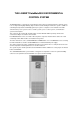
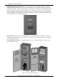
THE LIEBERT DataMate3000 ENVIRONMENTAL CONTROL SYSTEM The DataMate3000 is a small precise environmental control system specially designed for electrical system room cooling. Featuring high reliability, high sensible heat ratio and big air volume, the system is suitable for controlling the temperature and humidity (optional) in system or computer room to maintain a favorable environment for precise systems such as sensitive systems, process control systems, communication systems and computers.
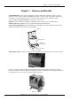
Chapter 1 Features and Benefits Chapter 1 Features and Benefits Computer Matched-Liebert systems are designed to create the environment required for computers, telecom and other sensitive electronic equipment. DataMate3000 provides complete control of temperature, humidity and air cleanliness on an around the clock basis, as well as the high sensible heat ratio required by sensitive 2 electronic equipment. Space Saving-Requires 5 square feet (.5m ) or less.
2 Chapter 1 Features and Benefits Intelligent Microprocessor Control- The system controller has a 128×64-matrix dot LCD screen with blue backlight. The man-machine-interface is easy-to-use. Multilevel passwords are configured to prevent unauthorized operation. The program is stored in non-volatile memory. The controller also has functions of high-voltage/low-voltage protection, phase failure protection and phase switchover in case of reverse phase rotation.
Chapter 2 Model Configuration Chapter 2 3 Model Configuration 2.1 Model Number Designations DM E 07 M C 1 DataMate3000 Version 1 DME3000 standard version 1 E1 DME3000 S series version 1 Unit Model Optional Features E Indoor unit C Cooling only C Standard outdoor unit O With electric reheat H With humidifier and reheat Capability Rate Main Power Supply 05 5kW M 380V/3 Ph/50Hz 07 7kW W 220V/1 Ph/50Hz 2.
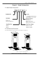
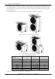
Chapter 2 Model Configuration The shadow in Figure 2-1 indicates a reasonable service access area. The indoor units can be installed against a wall. Air conditioners with heaters should keep a distance of minimum 150mm from combustible substance. When testing the air conditioner, the exterior fine pressure should be kept below 150Pa lest the air quantity should be low and the heater should overheat, The mechanical parameters of the outdoor units are shown in Figure 2-2, Figure 2-3 and Table 2-1.
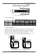
Chapter 2 Model Configuration 5 15 20 35 11 1750 ± 15 (blue) 14 13 24 50 12 2、3、4、5、6、7、8 1 10 9 1600 ± 15 (brown) 426 ± 1 Figure 2-4 15 Dimensions of heater (unit: mm) 2.
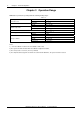
6 Chapter 2 Model Configuration Chapter 3 Operation Range DME3000 are provided for operating within the following working ranges: Table Installing position between indoor unit and outdoor unit Room air conditions Ambient temperature horizontal ≤50m vertical ΔH(1):-5m≤ΔH≤20m temperature 0°C ~30°C humidity 30%~80%RH standard outdoor unit -15°C ~+45°C with Lee-Temp unit -34°C ~+45°C <1000m (2) Altitude Power supply tolerances Storage conditions 3-1 voltage -15%~+15% frequency ±2Hz (3)
Chapter 4 Technical Data Chapter 4 Technical Data Table 4-1 Standard DME3000 Technical Data Air cooled Nominal Cooling Capacity (kW) Indoor Unit Model 7.5 12.
8 Chapter 4 Technical Data Table 4-2 DME3000 S Series Technical Data Air cooled Nominal Cooling Capacity (kW) Indoor Unit Model Power Supply 5.5 7.
Chapter 5 Microprocessor Control Chapter 5 9 Microprocessor Control The microprocessor control features an easy-to-use menu-driven LCD display. It monitors and displays the operation status of the precision cooling unit to maintain a reasonable environment in the controlled room. The menus, control features and parameter settings are described in this chapter. 5.1 LCD Screen LCD screen displays English menus with blue backlight.
10 5.3 Chapter 5 Microprocessor Control Setpoints The default setpoints have been configured before delivery. They are configured according to the general operation status or optional components. Change the defaults only when they do not satisfy the user’s requirement. Refer to Figure 5-1 for the setpoints and the value range. Users need to enter the password in corresponding level before changing the information such as setpoints, date, time, and so on (refer to section 5.4.4).
Chapter 5 Microprocessor Control 5.4 Control Screen 5.4.1 Off Screen 11 The LCD displays this screen after the system is powered on. In addition, it will be displayed by pressing the ON/OFF button during system operation, as shown in Figure 5-3. You can press the Left/Right button and the Enter button to select the display language. EMERSON 中 文 En g l i s h Figure 5-3 5.4.2 Off screen On Screen When the system is in automatic turn-on status after powered on, the LCD displays the On screen.
12 Chapter 5 Microprocessor Control If the password entered is incorrect, the user can view the menu but cannot change the parameters. The user can return to the Normal screen by pressing Esc button and enter the password again. If the password entered is correct, any parameter under the main menu can be changed. Note If press Enter button from the Password screen instead of inputting any password, the user can only view the menu and cannot change the parameters. 5.
Chapter 5 Microprocessor Control 5.6.2 13 Alarm History Select Alarm History from the Alarm Menu screen to view the Alarm History screen. The screen displays the detailed inactive alarm information or “No alarms” if no inactive alarm exists. The alarm No./the total number inactive, alarm name, the time/date occurrence are indicated for each alarm, as shown in Figure 5-10.
14 Chapter 5 Microprocessor Control Table 5-2 Alarm output logic Settings Alarm History Alarm Status Audible alarm OPEN Yes Yes Yes Alarm prompt Yes CLOSE Yes Yes No Yes STOP No No No No Note As the high pressure alarm, low pressure alarm and power failure alarm are major alarms, they cannot be set to STOP. 5.6.5 Custom Alarm The custom alarm settings will not be lost when power fails.
Chapter 5 Microprocessor Control 5.7 15 Setpoints The setpoints will not be lost when power fails. Select the Setpoints from the main menu and press Enter to configure the setpoints listed in Figure 5-16. TempStpt TempSens Hum Stpt Hum Sens 24°C 3°C 50%RH 5%RH Figure 5-16 Setpoints menu Use the Up/Down buttons to select a certain item and press Enter to access the input data field. Use the Up/Down buttons again to increase or decrease the digit. Press Enter to validate the new setpoint.
16 Chapter 5 Microprocessor Control Fan Co o l He a t L oSp d / De h um ON ON OFF OFF Hum Ho s T Sp a r e Sy s t em Figure 5-20 5.8.4 OF F OF F OF F No r m H i Pr ess Lo P r e s s Sho r t Cy c l e Un i t No r m No r m No r m No r m Output Status screen Run Time Run Time screen displays the total operation hours of the system. Press Up/Down buttons to scroll the items, as shown in Figure 5-21. Fan Co o l He a t H um 80 20 20 20 Figure 5-21 5.8.
Chapter 5 Microprocessor Control 17 1. Use Up/Down buttons to move the cursor to Teamwork in the System Setup menu, and press Enter to display the Teamwork sub-menu, as shown in Figure 5-26. Use Up/Down buttons to move the cursor to Cntl Board, and press Enter to set the control board number for communication with other control boards. It can be set from 0 to 15, and the default value is 0. Use Up/Down buttons to move the cursor to Unit No, and press Enter to set the unit number.
18 Chapter 5 Microprocessor Control Unit Status Hst Time Spr Time Chg Time Figure 5-29 SIG 24h 24h 30s Standby sub-menu 1) Use Up/Down buttons to move the cursor to Unit State in the Standby sub-menu, and press Enter to set the system to Hst Time (Duty unit), Spr Time (Standby unit) or Chg Time (Single unit). The default setting is HST. 2) Use Up/Down buttons to move the cursor to Host Time, and press Enter to set the operation cycle of the duty unit.
Chapter 5 Microprocessor Control Leve l Leve l Figure 5-32 On e Two 19 * * * * * * * * Change Password menu Use Up/Down buttons to move the cursor to the password to be changed and press Enter. Use Left/Right buttons to move the cursor to the digit to be changed, and then Up/Down buttons to change the value. Press Enter to validate the password or press Esc to abort. 5.9.6 Factory Reset Use Up/Down buttons to move the cursor to Factory Reset in the System Menu and press Enter.
20 Chapter 5 Microprocessor Control Da t a M a t e 30 0 0 Figure 5-36 Product Info screen Operation Help is not available at present. 5.10.2 Service Info Select Service Info from the Help Menu and press Enter to display the items listed in Figure 5-37.
Chapter 5 Microprocessor Control Appendix 1 21 Control System Menu Structure Main Menu Alarm Menu Setpoints System Status Temp Sens Temp / Hum Alrm History Alarm Setpoint Hum Sens Time / Date Hi Temp Operation Help Main fan Setup System Lo Spd/Dehum Hum Cp Start C/F Degree Cp MinOn Hum Control Cp MinOff Beeper Host Backlight Spare Contrast Hi Hum System Low Fanspeed Hi Press Temp compsen Power Fail Lo Press Short cycle Short Cycle Custom #1 Unit Custom #2 Fan Standby
22 Appendix 2 Wiring Diagram Appendix 2 Wiring Diagram Wiring Diagram Of DME3000 Standard DataMate 3000 Series Air Conditioner Technical Manual
Appendix 2 Wiring Diagram Of DME3000 S Series DataMate 3000 Series Air Conditioner Technical Manual Wiring Diagram 23
24 Appendix 2 Wiring Diagram Appendix 3 Spare Parts Indoor Unit Spare Parts: Code Spare Parts DME05WCE1 DME05WOE1 DME07WCE1 DME07WOE1 DME07MC1 DME07MO1 DME07MH1 DME12MC1 DME12MO1 DME12MH1 Dosage each unit Compressor 02520014 02520015 02520011 02520012 1 Compressor Capacitor 08030214 08030316 -- -- 1 Crankcase Heater 02510020 02510020 02510001 02510001 1 Inner Fan 32010123 32010123 32010111 32010111 1 Expansion Valve 27010009 27010002 27010002 27010003 1 1 Sight Glasse
Emerson Network Power Asia Pacific (Headquarters) T: 852-25722201 F: 852-28029250 Australia T: 1800-065345 China T: 86-755-86010808 Hong Kong T: 852-25722201 India T: 91-22-25807000 / 2388 Indonesia T: 62-21-2513003 Japan T: 81-3-54038594 Korea T: 82-2-34831502 Malaysia T: 603-7884 5000 New Zealand T: 64-3-3430235 Philippines T: 63-2-8934177 / 178 Singapore T: 65-64672211 Taiwan T: 886-2-2528 3535 Thailand T: 66-2-6178260 Vietnam T: 84-4-762 8908 Emerson Network Power.