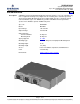
SAG584622000 System Application Guide Spec. No. 584622000 (Model DCS4830) Issue AB, November 18, 2009 Home SYSTEM OVERVIEW Description: A DC-DC Converter Module Mounting Shelf designed to mount in a 19” or 23” (nominal) relay rack or equipment mounting rack (configured for 19” mounting unless otherwise specified). The Converter Module Mounting Shelf, when equipped with up to three separately ordered Converter Modules (Spec. No.
SAG584622000 Issue AB, November 18, 2009 System Application Guide Spec. No. 584622000 (Model DCS4830) TABLE OF CONTENTS System Overview Ordering Information Specifications Physical Size Information Related Documentation SYSTEM OVERVIEW.................................................................................................................................................1 TABLE OF CONTENTS..........................................................................................................
System Application Guide Spec. No. 584622000 (Model DCS4830) SAG584622000 Issue AB, November 18, 2009 Home ORDERING INFORMATION Converter Module Mounting Shelf (Model DCS4830) Features ♦ The Converter Module Mounting Shelf accepts up to three (3) DC-DC Converter Modules. ♦ Two (2) blank panels are provided to cover unused Converter Module mounting positions. ♦ 19” rack mounting angles factory installed, 23” rack mounting angles supplied loose (can be adjusted for a 5” or 6” front projection).
SAG584622000 Issue AB, November 18, 2009 System Application Guide Spec. No. 584622000 (Model DCS4830) Home Wiring Notes Refer also to the next section, Wiring Illustrations. DC Input (+24V) Features ♦ Front accessed 1/4-20 x 5/8” studs on 5/8” centers are provided for installation of customer provided DC input leads terminated in 2-hole lugs. Ordering Notes 1) DC input lugs must be ordered separately. For lug selection, refer to the following table.
System Application Guide Spec. No. 584622000 (Model DCS4830) SAG584622000 Issue AB, November 18, 2009 Home DC Output (-48V) Features ♦ Two (2) 6-position 0A to 15A GMT Fuse Modules (for a total of 12 fuse positions) are provided for load distribution. ♦ Load and load return leads are connected to a screw-type terminal block located on the front of each GMT Fuse Module. ♦ Each GMT Fuse Module is equipped with six (6) dummy fuses and safety fuse covers.
SAG584622000 Issue AB, November 18, 2009 System Application Guide Spec. No. 584622000 (Model DCS4830) Home External Control and Alarms Features ♦ An external control and alarm circuit card is located behind the shelf’s top front access panel. This circuit card provides three sets of Form C relay contacts for external alarms, plus an ESTOP input. A terminal block is provided on the circuit card for customer connections. Restrictions Terminal block wire size capacity is 14 to 26 AWG.
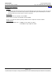
System Application Guide Spec. No. 584622000 (Model DCS4830) SAG584622000 Issue AB, November 18, 2009 Home Wiring Illustrations DC Input (+24V) DC Input Terminals Located Behind Insulating Shield (bend shield up to access terminals) Front Cover Captive Fasteners DC Input Terminals Top Cover (w/ insulating shield) removed in illustration for clarity only.
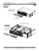
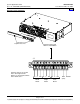
SAG584622000 Issue AB, November 18, 2009 System Application Guide Spec. No. 584622000 (Model DCS4830) Home DC Output (-48V) DC Output Leads Enter Here Front Door Captive Fastener Front View DC Output Terminal Blocks -48V Distribution Leads Load Return Leads DC Output Terminal Blocks Page 8 of 17 This document is property of Emerson Network Power, Energy Systems, North America, Inc.
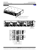
System Application Guide Spec. No. 584622000 (Model DCS4830) SAG584622000 Issue AB, November 18, 2009 Home External Control and Alarms Front Cover Captive Fasteners External Control and Alarm Terminal Block J1 All relay contacts are shown in the deenergized state. Relays are deenergized when in the alarm state. NC C NO NC C Minor Alarm Major Alarm NO NC C NO RTN ESTOP (24V) Fuse Alarm Page 9 of 17 This document is property of Emerson Network Power, Energy Systems, North America, Inc.
System Application Guide Spec. No. 584622000 (Model DCS4830) SAG584622000 Issue AB, November 18, 2009 Home SPECIFICATIONS 1.1 Output Ratings 1.1.1 Voltage: Nominal -48 volts DC, positive ground, non-adjustable. 1.1.2 Current: 10 amperes per DC-DC Converter Module, up to a total of 30 amperes per DC-DC Converter Mounting Shelf when three (3) Converter Modules are installed. 1.1.
System Application Guide Spec. No. 584622000 (Model DCS4830) SAG584622000 Issue AB, November 18, 2009 Home 1.2 Input Ratings 1.2.1 Voltage: 24 volts DC nominal. Input voltage range is 21 to 28 volts DC. 1.2.2 Filtering: Noise reflected back to the central office battery is less than 32 dBrnC. 1.2.3 Typical Input Data - When equipped with one Converter Module. (A) The output voltage of the DC-DC Converter Module is initially adjusted to 48 volts at 50% load and 24 volts DC input.
System Application Guide Spec. No. 584622000 (Model DCS4830) SAG584622000 Issue AB, November 18, 2009 Home 1.2.4 Typical Input Data - When equipped with three Converter Modules. (A) The output voltage of the DC-DC Converter Modules are initially adjusted to 48 volts at 50% load and 24 volts DC input. Input Voltage 21 VDC 24 VDC 28 VDC Percent of Full Load Input Current (Amps) Efficiency (%) Typical Heat Dissipation (BTU/Hr) 0 25 50 75 100 0 25 50 75 100 0 25 50 75 100 2.42 20.90 39.59 59.09 79.
System Application Guide Spec. No. 584622000 (Model DCS4830) SAG584622000 Issue AB, November 18, 2009 Home 1.3 Environmental Ratings 1.3.1 Operating Ambient Temperature Range: -20°C to +65°C (-4°F to +149°F). 1.3.2 Storage Ambient Temperature Range: -40°C to +85°C (-40°F to +185°F). 1.3.3 Humidity: This DC-DC Converter System is capable of operating in an ambient relative humidity range of 0 to 95%, non-condensing. 1.3.
System Application Guide Spec. No. 584622000 (Model DCS4830) SAG584622000 Issue AB, November 18, 2009 1.4.3 Home Output Protection: (A) Overvoltage Protection: Operation of a DC-DC Converter Module will automatically shut down and lock out if the output voltage of the module exceeds 115% to 125% of the nominal voltage. Manual restart is necessary after the overvoltage condition is corrected.
System Application Guide Spec. No. 584622000 (Model DCS4830) SAG584622000 Issue AB, November 18, 2009 Home PHYSICAL SIZE INFORMATION Overall Dimensions 17.37 Notes: 1. All dimensions are in inches, unless otherwise specified. 2. Weight in LBS. Shelf Net: 17 Shipping: 21 Converter Net: 3.2 Shipping: 5 3. Finish: Textured Gray. 4. Mounting angles adjustable for 5" or 6" front projection. 12.18 6.00 (note 4) Top View 3.48 18.32 19.00 22.32 23.00 Left Side View Front View 0.28 x 0.
System Application Guide Spec. No. 584622000 (Model DCS4830) SAG584622000 Issue AB, November 18, 2009 Home RELATED DOCUMENTATION Schematic Diagram: Wiring Diagram: Installation and User Instructions: SD584622000 T584622000 Section 6035 Page 16 of 17 This document is property of Emerson Network Power, Energy Systems, North America, Inc. and contains confidential and proprietary information owned by Emerson Network Power, Energy Systems, North America, Inc.
System Application Guide Spec. No. 584622000 (Model DCS4830) SAG584622000 Issue AB, November 18, 2009 Home REVISION RECORD Issue Change Number (ECO) AA AB LLP213133 LLP213431 Description of Change New Maximum heat dissipation value added. Date 10/22/09 11/18/09 Approved John Jasko John Jasko Joe Piwowar Jan 22, 2010 John Jasko Jan 25, 2010 Emerson Network Power, Energy Systems, North America, Inc.