Integrated Cabinet Solutions For Business-Critical Continuity™ DCF™ Optimized Rack System User Manual
IMPORTANT SAFETY GUIDELINES SAVE THESE INSTRUCTIONS This manual contains important instructions that should be closely followed during installation and maintenance of this unit. Read all safety instructions before attempting to assemble and install the DCF Optimized Rack System. Adhere to all warnings on the unit and in this manual. Follow all instructions. Read all warnings, cautions and instructions in this before attempting to move, lift, remove packaging from or preparing unit for installation.
TABLE OF CONTENTS IMPORTANT SAFETY GUIDELINES . . . . . . . . . . . . . . . . . . . . . . . . . . . . . . . . . . . . . . . . . . . . . . . . . .2 1.0 INTRODUCTION . . . . . . . . . . . . . . . . . . . . . . . . . . . . . . . . . . . . . . . . . . . . . . . . . . . . . . . . . .1 2.0 MAJOR COMPONENTS . . . . . . . . . . . . . . . . . . . . . . . . . . . . . . . . . . . . . . . . . . . . . . . . . . . .2 2.1 Frame . . . . . . . . . . . . . . . . . . . . . . . . . . . . . . . . . . . . . . . . . . . . .
FIGURES Figure 1 Figure 2 Figure 3 Figure 4 Figure 5 Figure 6 Figure 7 Figure 8 Figure 9 Figure 10 Figure 11 Figure 12 Figure 13 Caster plate . . . . . . . . . . . . . . . . . . . . . . . . . . . . . . . . . . . . . . . . . . . . . . . . . . . . . . . . . . . . . . . . . . . . . 2 Top cover for DCF Optimized Rack System 1100mm and 1200mm deep . . . . . . . . . . . . . . . . . . . . 4 DCF Optimized Rack System as shipped . . . . . . . . . . . . . . . . . . . . . . . . . . . . . . . . . . . . . . . . . . . .
Introduction 1.0 INTRODUCTION The highly versatile DCF Optimized Rack System provides an organized, secure, controlled environment in a single system for sensitive electronic equipment. The DCF Optimized Rack System is available in two heights—42U and 48U (78.1" and 88.6"; 1985mm and 2251mm).
Major Components 2.0 MAJOR COMPONENTS DCF Optimized Rack System will have all of the components addressed in this section. All components are finished with a textured powder coat, color is RAL 7021. 2.1 Frame The DCF Optimized Rack System is constructed of hot and cold rolled steel. Frame is light weight and strong with a 3000lb static load rating. 2.1.1 Adjustable Rails The DCF Optimized Rack System ships with 2 sets of 19" (EIA310-E) compliant rails.
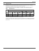
Major Components Table 2 Door dimensions, single door Door Dimensions, in (mm) Frame Size 42U 48U Table 3 Height 78.1 x 23.6 (2000 x 600) 78.1 x 31.5 (2000 x 800) 83.4 x 23.6 (2100 x 600) 83.4 x 31.5 (2100 x 800) 76 (1931.5) 87 (2198.2) Width Part Number 23 (586) Part # 546053G1L 31 (768) Part # 546053G2L 23 (586) Part # 546053G3L 31 (768) Part # 546053G4L Door dimensions, split doors Door Dimensions, in (mm) Frame Size 42U 48U 2.2.2 Height 78.1 x 23.6 (2000 x 600) 78.1 x 31.
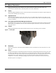
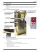
Major Components 2.2.3 Top Cover All DCF racks ship with top cover constructed of sheet metal. The top cover has cutouts for fan mounting, cabling, and cagenut installation which allows mounting of certain DCF accessories. Figure 2 2.3 Top cover for DCF Optimized Rack System 1100mm and 1200mm deep Mounting Hardware & Tools Hardware to install additional accessories ships with the DCF rack.
Installation 3.0 INSTALLATION 3.1 Inspection Upon receiving a DCF Optimized Rack System, examine the packaging for any signs of mishandling or damage. If any damage is noted, notify your local Emerson® representative and your carrier immediately.
Installation 3.3 Unloading the DCF Optimized Rack System Before unloading a DCF Optimized Rack System, note the weight of the model (see 5.0 Specifications. Use at least two people when moving the unit. 1. Using a pallet jack or forklift, move the DCF Optimized Rack System on its pallet to the installation location. 2. Cut the shrink wrap and remove all packaging. 3. Use a 14mm socket or a 14mm wrench to remove the lag bolts securing each shipping bracket to the shipping pallet.
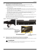
Installation 3.4.1 Installing the Edge Guard 1. Press edge guard to top cover cut outs by pressing along the edge of the cut out opening. 2. Trim excess edge guard with a pair of scissors after the edge guard has been completely applied around the opening. 3. Repeat Steps 1 and 2 for remaining cut outs. Figure 5 3.4.2 Applying the edge guard Front- and Rear-Mount 19" EIA Rails—Position and Attach Front- and rear-mount 19" EIA rails are installed in DCF racks at the factory at 29.13 inches (740mm).
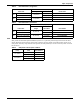
Installation Figure 6 19" EIA rail repositioning 19" EIA rail face Frame member where 19" EIA rail is attached Holes in frame member are 6.35mm apart Loosen this screw to let rail slide Position 19" EIA Rails on 800mm Cabinets 1. Determine the proper location of the 19" EIA rails. 2. Loosen the two screws that secure the node adjustment brackets to the bottom frame member, then slide the bracket down. Repeat on the other two node adjustment brackets attached to the frame and center support member. 3.
Installation 3.4.3 Door—Remove and Reverse DCF doors are removable for convenience when installing or maintaining equipment. The DCF front door is also reversible, so the single-door may be opened in a more convenient direction if the rack is near a wall or other equipment. Doors are supported by two hinges and held in place by gravity. They can be lifted off and reinstalled without tools (see Figure 8). NOTE Doors are easier to remove if they are open at a 90° angle to the DCF cabinet.
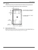
Installation Figure 9 Alternate door hinge position and grounding wire location Ground Wire Bolt Hole and Symbol Hinge Location when Reversing Door 3.4.4 Side Panels The DCF uses dual split side panels fashioned from sheet metal. The lower panel hangs on a frame member and the upper panel hangs on the rack frame. Each panel is secured with a lock. The arrangement makes the panels simple to remove and replace, making it easier to install equipment.
Installation 3.5 Power Distribution Unit Mounting Power distribution units may be mounted multiple ways in the DCF Optimized Rack System rack. They may be mounted on the rails or attached to mounting brackets: • 42U full height PDU/cable management mounting brackets (4"W) (Part # 546076G1L) • 48U full height PDU/cable management mounting brackets (4"W) (Part # 546077G1L) 3.6 Full-Height PDU/Cable Management Brackets 3.6.1 Install a Full-Height PDU/Cable Management Bracket 1.
Installation 3.7 Baying Configuration Two or more DCF cabinets of the same height can be bayed with the supplied baying brackets. The brackets have three holes: one that connects to the DCF, one that puts the cabinets on 24" (609.6mm) centers and one that puts the cabinets on metric centers. Connecting DCF racks is easier if the units have been moved to their final installation position before beginning to attach them in a cluster.
Periodic Maintenance 4.0 PERIODIC MAINTENANCE Your DCF Optimized Rack System cabinet requires no special maintenance. It should be cleaned periodically, more frequently if the air in the vicinity is not filtered for particulates. Dust should be cleaned from installed equipment according to the manufacturer’s recommendations. Clean the interior of the cabinet with a dry cloth.
Specifications 5.0 SPECIFICATIONS Figure 13 DCF Optimized Rack System model numbers F 2 6 1 PRODUCT F = DCF Optimized Rack System 1 1 2 2 1 FRONT DOOR 1 = Single, Perforated Door HEIGHT 2 = 42U (2000mm) 8 = 48U (2250mm) WIDTH 6 = 600mm (23.6") 8 = 800mm (31.5") REAR DOOR 2 = Split, Perforated Door SIDE PANELS 2 = 2 Side Panels FACTORY-INSTALLED OPTIONS 1 = Factory-Installed Options Placeholder 1 DEPTH 1 = 1100mm (43.3") 2 = 1200mm (47.
Ensuring The High Availability Of Mission-Critical Data And Applications. Emerson Network Power, a business of Emerson (NYSE:EMR), is the global leader in enabling Business-Critical Continuity™ from grid to chip for telecommunication networks, data centers, health care and industrial facilities.