
Freezer User's Manual

11-16 • E2 RX/BX/CX I&O Manual 026-1610 Rev 13 14-SEP-2011
case controller has no usable case temperature input
value), the case controller will keep the valve percentage
at its last known good value and continue operation as nor-
mal. For instance, if the valve was at 75% when the case
temp sensor(s) failed, the valve will remain at 75% until it
the failure is corrected. All other case control functions
will continue functioning as normal.
11.4.12 Wiring
Input and output wiring for a case controller is dis-
cussed in detail in Section 4, E2 Hardware Setup. Before a
Case Control Circuit application may begin functioning,
all case controllers must be properly connected to its case
inputs and outputs, and each case controller must be com-
missioned and properly communication on the Echelon
Network (see Section 4, E2 Hardware Setup for instruc-
tions on how to do this).
11.4.13 Setting Up An Individual
Case Controller
Most of the data required for a case controller to begin
operation are supplied to it by associating the controller
with an E2. However, in some cases, it will be necessary to
change some of the parameters in an individual case con-
troller. Some instances where it will be necessary are:
•When the configuration for the inputs needs to be
changed (i.e., when the case has a sensor or
switch configuration that cannot be satisfied by
the default configuration).
•When a valve other than an Emerson Flow Con-
trols ESR-12, ESR-20, or ESV is being used.
Each case controller is programmed by default to
operate Emerson Flow Controls brand valves. If
the valve type is different, the valve control
parameters must be changed in the case controller
software.
•When the PID settings that determine the valve
aperture or closure require alteration.
When necessary, the case controller can be altered in
either of two ways. You can change settings in a case con-
troller application in E2 via the front screen. Or, you can
use a Hand-held Terminal to log in to the CC-100 or CS-
100 directly, and make temporary
changes that will not be
saved.
11.4.14 Associating Case Controllers
with Case Circuit Control Applica-
tions
Before you can program a Case Control Circuit with
the necessary parameters, you must associate the appropri-
ate CC-100s, CS-100s, EC-2s, and CCBs with the Case
Control Circuit application you will be programming.
To access the CC/CS-100 Case Control Association
Screen:
1. Press
for the Main Menu.
2. Press
for System Configuration.
3. Press
for the Network Setup menu.
4. Press
for Case Control Associations. The
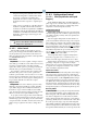
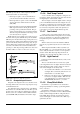
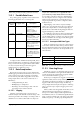
Case Control Association screen should look like
Figure 11-7:
This screen lists all of the CC-100s, CS-100s, EC-2s,
and CCBs defined in this E2. Each one is listed with its
name, its node number, the application name of the case
controller’s application, and the associated circuit name.
To associate a case controller with its circuit, move the
cursor into the Circuit field of the controller you wish to
associate, and press the key. The Application Selec-
tion menu will list all of the Case Control Circuit applica-
tions in the E2. Choose the desired circuit and press
or to select. Repeat this process until all case con-
trollers are associated with Case Control Circuit applica-
tions.
11.5 Logging Groups
A logging group is a set of application property inputs
and outputs whose values are recorded (logged) with the
same parameters. Parameters include the interval, how
often the property values are logged (for example, every
30 seconds, every 5 minutes, etc.), the duration of the log
(for example, 2 days, 30 days, 100 days, etc.), and the res-
Figure 11-7
- CC/CS100 Circuit Association Screen (RX-400)