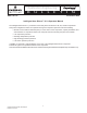
Application Engineering Application Engineering B L LL E L T EI BU U N T I N AE November 2006 AE8-1337 R1 Intelligent Store Discus™ V1.0 Operators Manual The Intelligent Store Discus™ product line has recently been introduced on 2D, 3D, and 4D compressors.
AE8-1337 R1 Emerson Climate Technologies Intelligent Store™ Discus® Operator’s Manual
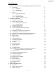
AE8-1337 R1 Table of Contents 1 2 3 4 Overview of Emerson Climate Technologies Intelligent Store™ Discus® 1.1 Functionality 1.1.1 Diagnostics 1.1.2 Communications 1.1.3 Fault History 1.2 Features 1.2.1 Compressor Protection 1.2.2 Remote Reset 1.2.3 Failsafe Operation 1.2.4 Welded Contactor Protection Installation Instructions 2.1 Mounting and Installation 2.2 Terminal Box Connections 2.2.1 Current Relay Connections 2.2.2 Fan Connections 2.3 Controller Requirements 2.4 Communications Network 2.
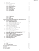
AE8-1337 R1 4.3 4.4 5 Startup Codes Status Code Troubleshooting 4.4.1 Normal - Off 4.4.2 Normal - Running 4.4.3 Demand Cooling Injecting 4.4.4 Low Suction Pressure 4.4.5 Low Oil Pressure 4.4.6 Motor Protection Trip 4.4.7 Welded Contactor 4.4.8 Low Supply Voltage 4.4.9 Module Failure 4.4.10 Discharge Pressure 4.4.11 Discharge Temperature 4.4.12 Loss of Communication 4.4.13 Disabled by Rack Controller 4.4.14 Phase Loss 4.4.15 No 3-Phase Power 4.4.16 No Code 4.4.
AE8-1337 R1 1. Overview of Emerson Climate Technologies Intelligent Store™ Discus® Compressor The Intelligent Store™ Discus® product line is now available on 2D, 3D and 4D compressors and integrates a number of important sensing and compressor protection functions. This product provides a Network Communications Interface (NCI) for on/off control of the compressor, capacity modulation and for communication of compressor status to the Computer Process Controls™ (CPC) E2 rack controller.
AE8-1337 R1 tions can be a powerful tool for diagnosing system problems. The fault history and the record of run cycles maintained in the Intelligent Store™ Discus® memory cannot be re-set. If a compressor is replaced, the E2 notebook feature (see section 5.7 of this manual) should be used to maintain a record of faults at the time of replacement (if the Intelligent Store™ Discus® front box is transferred to the new compressor).
AE8-1337 R1 2. 2.2 Installation Instructions Emerson Climate Technologies, Inc. requires that all customers review the recommended guidelines in the published Application Engineering Bulletins, and ensure that best engineering practices are followed in the use of Copeland® brand compressors. Emerson Climate Technologies, Inc. Application Engineering Bulletins can be found on our website, EmersonClimate.com under the section titled “Online Product Information”.
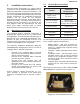
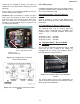
AE8-1337 R1 2.2.1 Current Relay Connections • 2D and 3D compressors have a current relay in the terminal box (refer to figure 2.1 above). The current relay is used to detect an open motor protector. Route one motor power lead through the relay as in figure 2.2. Note: 2D TFD and TFE compressors 6 HP or smaller should pass the power lead twice through the coil. The minimum amp draw that the relay can properly sense is 5.5 amps. Figure 2.3 4D Fan Installation Figure 2.2 Current Relay Wiring 2.2.
AE8-1337 R1 designed for commercial HVAC and Refrigeration applications. RS-485 hardware connections are used at the network terminations and at each node (compressor). The Intelligent Store™ Discus® communication cable terminates in the E2 Controller on the Network Interface Board, and is routed to each of the compressors in a daisy-chain format. Refer to figure 2.6 and figure 2.8. Figure 2.8 Two Rack Daisy-Chain One E2 controller can control 4 suction groups, with up to 16 stages in each suction group.
AE8-1337 R1 Grommets are included to minimize the chance of chaffing where the cable passes through sheet metal openings. Refer to figure 2.11 for details regarding the communication board jumper positions. Important! Note that RS485 is polarity sensitive. “Pos” wires must connect to other “Pos” terminals, and “Neg” wires must connect to other “Neg” terminals. The shield wire is connected to the center terminal, or “0 volt” position. Refer to section 4.4.12 for voltage specifications. 2.5.
AE8-1337 R1 3. Intelligent Store™ Discus® Commissioning Procedure Important Note: The following commissioning instructions (sections 3.0 through 3.9) pertain to E2 controllers with version 2.21 or later firmware. If you have an earlier version of firmware we recommend that you upgrade to the latest version available. For commissioning instructions pertaining to E2 controllers with firmware revisions of 2.07 through 2.20 refer to sections 3.10 through 3.20 of this document.
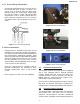
AE8-1337 R1 Figure 3.1 Network Setup Screen Navigation (Key Sequence 7-7-2) Figure 3.2 ISD Compressor Setup Screen Navigation (Key Sequence 5-35) 3.0 Network Setup Begin the process by logging on. To do this press the Log In/Out button on the E2. When prompted, enter “USER” in the username field and “PASS” in the password field. To access the menu shown in figure 3.1: 1. 2. 3. 4. Press Press Press Press menu to open the Main Menu. 7 (System Configuration). 7 (Network Setup).
AE8-1337 R1 Figure 3.4 Controller Setup Screen Figure 3.5 Controller Setup Screen (Following Node Recovery) 3. Verify that the number of ISD devices listed on the Controller Setup Screen matches the number of devices connected to the E2. 6. Once the first ISD device has been successfully commissioned, turn it OFF. At this point you must choose how you want the ISD devices to be displayed in the E2.
AE8-1337 R1 This will open the suction group setup screen as shown below in figure 3.6: account for two stages. A compressor without an unloader will count as one stage. To continue the suction group setup process: 1. Press F2 (Next Tab) until the Comp Setup screen is displayed. 2. Under Type, select Comp for compressor or Unld for unloader. 3. Under HP/Amps enter the compressor horsepower for each stage. 4. If run proofing is desired, select Yes under Proof. Figure 3.
AE8-1337 R1 When these steps have been completed, the compressor setup screen should look like figure 3.7 below: 3.3 Configuring Associations The next step links the ISD devices to the appropriate compressor/stage in the suction group. Access the association screen from the main menu by pressing 7 (System Configuration) followed by 7 (Network Setup) followed by 7 (ISD Associations). Once this has been done the screen should look like figure 3.8 below: Figure 3.
AE8-1337 R1 4. Highlight the appropriate suction group and press F5 (Setup). 5. Press F2 (Next Tab) until the Comp Setup tab is highlighted. 6. Select Yes under the Proof column. 7. Press F2 (Next Tab) until the More tab is highlighted. Once the More tab has been selected, the display should look like figure 3.13. 8. Press F3 (Edit). 9. Press 1 (Alternate I/O Formats). 10. Press 2 to select the Controller / Application / Property format. Figure 3.
AE8-1337 R1 compressor OFF. In the case where the module is set for failsafe OFF the compressor will not run until communications have been re-established with the E2. In the case where the module is set for failsafe ON, the compressor will continue to run until communications have been re-established with the E2. In this case all compressor protection provided by the module will still function as needed. The screen should look like figure 3.15 below.
AE8-1337 R1 3.10 Intelligent Store™ Discus® Commissioning Procedure for E2 Firmware Revisions 2.07 through 2.20 Each Intelligent Store™ Discus® Compressor module (referred to as “CST” in the E2) is connected to the E2 via the RS-485 communications network. As with other devices, the module must first be “commissioned” to establish communications with the rack controller.
AE8-1337 R1 Begin the process by logging on. To do this press the Log In/Out button on the E2. When prompted, enter “USER” in the username field and “PASS” in the password field. To access the screens shown in figures 3.17 and 3.18: 1. 2. 3. 4. 5. Press Press Press Press Press menu to open the Main Menu. 7 (System Configuration). 7 (Network Setup). 1 (Online Status). F1 (CST Status). After communications have been established with a module, the E2 screen will update and list the device as Node Found.
AE8-1337 R1 To rename the modules, access the CST Setup Screen: 1. Press menu to open the Main Menu. 2. Press 5 (Configured Applications). 3. Press 35 (CST Compressors). Figure 3.
AE8-1337 R1 Sample Rack with Intelligent Store™ Discus® Compressors - 25° Suction 3. Enter the Board : Point information for the suction pressure transducer. This information can be found by locating the appropriate suction pressure transducer and determining its location on the I/O board wired into the rack controller.
AE8-1337 R1 3.16 Remote Reset In the event of an oil pressure or discharge temperature lockout a manual reset is required to restart the compressor. This can be accomplished by pressing the reset button on the front of the Intelligent Store™ Discus® module or by remotely resetting the module through the CPC UltraSite™ monitoring software program. In order to enable this remote reset option, follow these steps: 1. From the CST Setup Screen shown in figure 3.
AE8-1337 R1 Note: For a compressor equipped with an unloader the horsepower should be divided between the compressor and unloader stages. A compressor with an unloader can be considered to be two different compressors from a control standpoint. When the suction group status screen shows the unloader to be “off” and the comp (compressor) to be “on”, the compressor is running “unloaded”, i.e.
AE8-1337 R1 Sample Rack with Intelligent Store™ Discus® Compressors - 25° Suction - 15° Suction 4DL3A150L-TSK 04I35625R 3DRHA100E-TFD 04I00300R 4DS3A220E-TSK 04I35631R 3DRHA100E-TFD 04I00439R Address Subnet: 15 Node: 2 Subnet: 15 Node: 5 Subnet: 15 Node: 4 Subnet: 15 Node: 3 Subnet: 15 Node: 1 Compressor Name RACK1COMP1 RACK1COMP2 RACK1COMP3 RACK2COMP1 RACK2COMP2 Comp1 Comp2 Comp3 (unloader) Comp4 Comp5 (unloader) Comp1 Comp2 (unloader) Comp3 Stages Note: “Comp Setup’ refers to the
AE8-1337 R1 Sample Rack with Intelligent Store™ Discus® Compressors - 25° Suction - 15° Suction 4DL3A150L-TSK 04I35625R 3DRHA100E-TFD 04I00300R 4DS3A220E-TSK 04I35631R 3DRHA100E-TFD 04I00439R Address Subnet: 15 Node: 2 Subnet: 15 Node: 5 Subnet: 15 Node: 4 Subnet: 15 Node: 3 Subnet: 15 Node: 1 Compressor Name RACK1COMP1 RACK1COMP2 RACK1COMP3 RACK2COMP1 RACK2COMP2 Comp1 Comp2 Comp3 (unloader) Comp4 Comp5 (unloader) Comp1 Comp2 (unloader) Comp3 Stages Once the Welded Contactor associa
AE8-1337 R1 4. Compressor Status Codes The LED on the Intelligent Store™ Discus® front box is designed to provide a rapid assessment of the compressor’s operation condition. The LED codes also provide some basic diagnostics to aid troubleshooting of the system or compressor. Figure 3.33 Suction Group Setup Screen The E2 will default to a (Board / Point) application. Before proofing can be programmed the E2 must be changed to accept a (Controller / Application / Output) format by following these steps: 1.
AE8-1337 R1 • Under normal operating conditions the code will switch between Injection Mode (2) and Normal (1) when not using demand cooling. 3 30 Second Reset - After initial power-up or pressing the reset button, a 30 second initialization takes place. The flashing numbers indicate the subnet and address labels, and may be used to verify that all segments of the LED function. Self-diagnostics are performed during this time. The compressor will remain off during the reset period.
AE8-1337 R1 compressor has been off for several seconds will not activate this code. 9 Module Supply Voltage Trip - If the module supply voltage drops below 170 volts for 2 seconds, the compressor is shut down to prevent contactor chatter. When the control voltage rises above 180 volts for 2 seconds, the module will enable the compressor to run again. • A b Disabled by Rack Controller - The compressor is disabled until the module stops receiving this command from the rack controller.
AE8-1337 R1 4.2 Status Code Table Status Code -STEADY- 0 1 2 3 4 Description Index of Details Normal - Off 4.4.1 Normal - Running 4.4.2 Normal - Demand Cooling Injecting 4.4.3 Low Suction Pressure Cutout 4.4.4 30 Second Reset -FLASHING- 5 6 7 8 9 A b C Low Oil Pressure Warning 4.4.5 Low Oil Pressure Lockout 4.4.5 Motor Protection Trip 4.4.6 Welded Contactor Warning 4.4.7 Compressor Module Supply Voltage Trip 4.4.8 Compressor Module Failure Lockout 4.4.
AE8-1337 R1 30
AE8-1337 R1 31
AE8-1337 R1 32
AE8-1337 R1 33
AE8-1337 R1 34
AE8-1337 R1 Figure 4.
AE8-1337 R1 36
AE8-1337 R1 37
AE8-1337 R1 38
AE8-1337 R1 39
AE8-1337 R1 Accessory Fuse Figure 4.
AE8-1337 R1 Figure 4.
AE8-1337 R1 Flashing d Loss of Communication Mode (continued) 2.3 to 2.6 VDC Communication Troubleshooting • DC Voltage 2.3v - 2.6v (all devices must be connected to the communications network) • Voltage between 485+ and 485- is typically less than 0.3vdc. • An open wire, poor connection or misplaced jumper will affect voltage. Touch points to measure voltage Communication Board Troubleshooting The communication board is a sacrificial element to protect the main board from damage due to voltage spikes.
AE8-1337 R1 Determine Reason Einstein™ System Override Set to “On” Correct Reason and Set Einstein™ System Override to “Off” 43
AE8-1337 R1 Figure 4.4 3D Voltage Sensor Connections Figure 4.
AE8-1337 R1 Contactor Fuse Figure 4.
AE8-1337 R1 46
AE8-1337 R1 47
AE8-1337 R1 5. Maintenance Procedures for Intelligent Store™ Discus® Compressors Emerson Climate Technologies, Inc. requires that all customers review the recommended guidelines in the published Application Engineering Bulletins, and ensure that best engineering practices are followed in the use of Copeland® brand compressors. Emerson Climate Technologies, Inc. Application Engineering Bulletins can be found on our website, EmersonClimate.com under the section titled “Online Product Information”.
AE8-1337 R1 Intelligent Store™ Discus® Compressors are lower than for standard demand cooling compressors. This is to compensate for the probe location used on the Intelligent Store™ Discus®. The actual peak gas temperatures inside the head are correspondingly higher and will be at the standard demand cooling levels during injection start, injection stop and at the maximum trip temperature.
AE8-1337 R1 5.1.3 Coil Inspection and Replacement (2D / 3D) Refer to figure 5.1 for the location of the injection coil. The coil may be removed by unplugging the harness from the coil and lifting the coil. The retention snap on the top of the coil is held in place by an internal spring and will snap off with sufficient lifting force. Do not lose the retention snap! Remove Head Cover Screws The resistance of a good coil should be 490 Ohms to 600 Ohms.
AE8-1337 R1 5.1.
AE8-1337 R1 6. Lower the side box to provide wrench clearance to the injection valve bolt. 8. Remount the side box by installing screws “A” and “B.” 7. Install a new valve, using new gaskets and torque to 25 - 30 ft-lb. Note: In an emergency, gaskets may be re-used if there is no apparent damage to the gasket such as tearing or delamination. 9. Install the injection coil and terminal box harness connections (push them in until a distinct “snap” is heard).
AE8-1337 R1 5.2 Compressor Replacement - 2D and 3D 5.2.1 Removal of the Compressor Note: The following instructions assume the same front module is being used on the new compressor. If the module is being replaced, refer to module change-out procedures for start-up procedures. Steps with an * indicate they pertain to module replacement instructions in section 5.3.
AE8-1337 R1 8. Unscrew the high and low pressure cutout switches. 9. Lift the demand cooling coil off of the injection valve (if present). 5. Mount injector valve to the adapter on the body. Using 2 gaskets (under the bolt flange and between the injector and the adapter) - torque the bolt to 25 - 30 ft-lb. 6. Put the side box on, loosely fitting screw “B.” 10. Unplug the oil pump sensor lead from the oil pump sensor. * 11. Remove 2 screws “A” and housing cover nuts holding front box (2). * 12.
AE8-1337 R1 5.3 Module Replacement for 2D / 3D 5.4.1 Compressor Replacement Refer to section 5.6.1, “Determine the Replacement Module Part Number”. Note that the failed module should be returned to the wholesaler to prevent payment of a core charge. Refer to section 5.2 (“Compressor Replacement for 2D and 3D”) for module removal instructions. Remove the module by following these steps in section 5.2 (the module removal steps are marked with an asterisk *): 1.
AE8-1337 R1 switch with a Schraeder depressor (deflator). Refer to the parts list in Appendix C. • Connect the blue “LPCO” leads to the low pressure switch. Verify pressure setting on the switch. When replacing the switch, use only an Emerson Climate Technologies, Inc. approved pressure switch with a Schraeder depressor (deflator). Refer to the parts list in Appendix C. 9. Refer to section 3.4, Compressor Naming, to edit the E2 for changes to the compressor serial number. 5.4.
AE8-1337 R1 8. Installation of a new front box will be the reverse of these steps. 9. If you are replacing a module that has only one fuse in the side, or perhaps no fuse, you must not re-use the field retrofit “snubber” connected to the discharge pressure switch. Discard the snubber it is not needed with the twin-fuse module. Remove Head Cover Screws 3. Unplug all harness connections, including the oil pressure sensor harness. 4.
AE8-1337 R1 7. Procedures to remove the head are the same as for any other Discus® compressor. 8. Installation of the module will follow the removal steps in reverse. Replacement will be the reverse of these steps. 5.5 Serial Number Change after Compressor Replacement After the compressor has been changed out and the Intelligent Store™ Discus® components are put back in place, the E2 should be edited to reflect the new compressor S/N, and perhaps the model number that is appropriate.
AE8-1337 R1 5.6 Replacement Module Information The module P/N will be 985-0102-xx, where “xx” is the node number. 5.6.1 Determine the Replacement Module Part Number When ordering a replacement module (front box) the address (node number) is required. The replacement part number reflects the node number that is pre-programmed into the module. There are several screens on the E2 that display the node number of the compressor. An example is the online status screen: 1. 2. 3. 4.
AE8-1337 R1 either a compressor or module is replaced. In this way a record can be maintained and the user will be able to assess the true history of the compressor. Using the E2 Notebook feature is discussed in section 8.7.6 of the E2 Operation Manual. 5.8 Pressure Switch Replacement The discharge and pressure switch adapters have Schraeder valves in them. It is not necessary to evacuate the compressor before replacing a switch. It is imperative that an Emerson Climate Technologies, Inc.
AE8-1337 R1 Appendix A A-1 Wiring Figure A.1 Wiring Diagram of Module, Harness and Deutsch Plugs in Terminal Box Figure A.
AE8-1337 R1 A.2 Fusing View From Side Box Squeeze These Tabs to Remove Plug Figure 6.1 Low Voltage Plug 5 Volts High Voltage Plug 230 Volts View of Terminal Box Accessory Coils (1/2 amp) Use Bussman AGC - 1/2A Figure 6.
AE8-1337 R1 (1/2 amp) for the accessory coils, and one fuse (2 amp) for the contactor coil (refer to figure 6.1). Always use a fast-blow fuse for replacement. When replacing a module that has only one fuse on the module (or perhaps no fuse), remove the contactor coil fuse that is found in the terminal box (refer to figure 6.2). There may also be an accessory fuse in the side box (2D / 3D) that may be discarded. Inspect fuses if the contactor fails to load, or if an accessory will not activate. A.
AE8-1337 R1 Appendix C Aftermarket Parts Service # Description 962-0902-00 Emerson Climate Technologies Intelligent Store™ Discus® Side Box. Includes side box and mounting hardware. For usage on specific Copeland® Brand 3D Discus® Compressors. 962-0900-00 Emerson Climate Technologies Intelligent Store™ Discus® Side Box. Includes side box and mounting hardware. For usage on specific Copeland® Brand 2D Discus® Compressors. 985-0125-00 High Pressure Cutout Switch.
AE8-1337 R1 905-0911-00 Electrical Terminal Box Cover. Cover Only. For usage with specific Copeland® Brand 3D Discus® Compressors with Emerson Climate Technologies Intelligent Store™ Discus® Module. Includes 052-0837-00 wiring diagram. 905-0911-01 Electrical Terminal Box Cover. Cover Only. For usage with specific Copeland® Brand 3D Discus® Compressors with Emerson Climate Technologies Intelligent Store™ Discus® Module. Includes 052-0803-00 wiring diagram.
AE8-1337 R1 985-0102-10 Emerson Climate Technologies Intelligent Store™ Discus® Module- Node 10. For usage on specific Copeland® Brand 2D, 3D and 4D Discus® Compressors. Includes front box assembly and wiring harness. 985-0102-11 Emerson Climate Technologies Intelligent Store™ Discus® Module- Node 11. For usage on specific Copeland® Brand 2D, 3D and 4D Discus® Compressors. Includes front box assembly and wiring harness.
AE8-1337 R1 Appendix D 3D Intelligent Store™ Discus® Reference Drawing 67
AE8-1337 R1 2D Intelligent Store™ Discus® Reference Drawing 68
AE8-1337 R1 4D Intelligent Store™ Discus® Reference Drawing 69
AE8-1337 R1 Appendix E Technical Support For technical support or assistance in resolving issues with the Intelligent Store™ Discus® Compressor Module or with the E2 contact the Computer Process Controls™ support line. Technical support can be reached at (770)-425-2724 in the Atlanta, GA metro area or toll free at 1-800-829-2724.
AE8-1337 R1 1675 West Campbell Road Sidney, OH 45365 (937) 498-3011 EmersonClimate.com 2006CC-15 R2 (10/06) Emerson®, Emerson. Consider It Solved™, Emerson Climate Technologies™ and the Emerson Climate Technologies™ logo are the trademarks and service marks of Emerson Electric Co. and are used with the permission of Emerson Electric Co. Sentronic+™, Discus®, Copeland®, and the Copeland® brand products logo are the trademarks and service marks of Emerson Climate Technologies, Inc.