
Data Sheet


D3 Valve
D103269X012
Product Bulletin
51.2:D3
February 2014
5
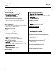
Table 2. EMC Summary Results - Immunity
PORT PHENOMENON BASIC STANDARD TEST LEVEL PERFORMANCE CRITERIA
(1)
Enclosure
Electrostatic discharge (ESD) IEC 61000-4-2
4kV Contact
8kV Air
A
Radiated EM field IEC 61000-4-3
80 to 1000 MHz @ 10V/m 1kHz AM at 80%
1400 to 2000 MHz @ 3V/m 1kHz AM at 80%
2000 to 2700 MHz @ 1V/m 1kHz AM at 80%
A
(2)
/B
Rated power frequency
magnetic field
IEC 61000-4-8 30 A/m @ 50 and 60 Hz A
I/O signal/ control
Burst IEC 61000-4-4 1kV A
Surge IEC 61000-4-5 1kV cable shield, and line to ground A
Conducted RF IEC 61000-4-6 3V 150 kHz to 80 MHz at 3 Vrms A
Performance criteria is +/- 5% stem position
1. A= No degradation during testing. B = Temporary degradation during testing, but is self recovering.
2. Criteria A with conduit on DC and I/O cables, Criteria B without conduit
Table 3. Fisher D3 Maximum Shutoff Pressure Drops (Pneumatic)
ACTUATOR
DESIGN
FLOW
DIRECTION
ACTUATOR
ACTION
INPUT SIGNAL
NUMBER OF
SPRINGS
MAXIMUM nP (PSI) PER PORT SIZE (INCH)
psi 0.375 0.75 1.00
Pneumatic
Up
Spring-to-Close
0-20 3 2250 544 341
0-35 6 2250 1504 999
Spring-to-Open
0-20 2 2250 935 608
0-35 2 2250 2250 2094
Down
Spring-to-Close
0-20 2 1558 1800 950
0-35 3 2250 2250 2250
Spring-to-Open
0-20 2 2250 1700 939
0-35 3 2250 2250 1575
Table 4. Fisher D3 easy-Drive Maximum Shutoff Pressure Drops (Electric)
ACTUATOR DESIGN FLOW DIRECTION
MAXIMUM nP (PSI) PER PORT SIZE (INCH)
0.375 0.75 1.00
Electric
Up 2250 1714 1114
Down 2250 2250 1948
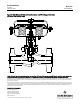
Figure 1. FloPro Adjusts to Vary Flow Capacity (Shown with Valve Plug in Seated Position)
FULL CAPACITY SETTING (FACTORY SET)
15 mm (0.6 INCH) TRAVEL
Note: Use the widely-spaced travel indicators, as shown
on the left portion of this view.
REDUCED CAPACITY SETTING
10 mm (0.4 INCH) TRAVEL
CLOSED
50%
100%
CLOSED
50%
100%
STEM CONNECTOR
INDICATES TRAVEL
STEM CONNECTOR
INDICATES TRAVEL
Note: Use the closely-spaced travel indicators,
as shown on the right portion of this view.
Note:See Fisher Catalog 12 for flow coefficients. Full capacity coefficientsare shown as 100 percent valve opening. Reducedcapacity coefficientsare shown as 60 percent
valve opening.