Rosemount Analytical NGA 2000 Software Manual MLT Analyzer MLT Analyzer Module (combined with NGA 2000 platform / MLT analyzer / TFID analyzer or customer-developed control unit) Software Version 3.2.X 2nd Edition 07/98 Catalog No.: 90 003 482 Managing The Process Better 90003482(2) [NGA-e (MLT-Software 3.2.
Rosemount Analytical This Operation Manual includes information about the operation of the instrument. Information about the additional indications and notes regarding maintenance, troubleshooting and repair are found in the accompanying Maintenance & Operation Manual. Troubleshooting, component replacement and internal adjustments must be made by qualified service personnel only. Fisher-Rosemount GmbH & Co does not take responsibility for any omissions or errors in this manual.
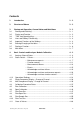
Contents 1 Introduction 1- 1 2 Structure of Menus 2- 1 3 3.1 3.2 3.3 3.4 3.5 3.6 3.7 3.8 Startup and Operation, General Notes and Main Menu 3Starting and Initializing ................................................................................... 3 Display and Function...................................................................................... 3 "TAG" and Operating Keys ............................................................................ 3 Lines and Softkey Functionality .......
5 Analyzer and I/O-Module Expert Configuration 5- 1 5.1 Analyzer Module Setup 5- 3 5.1.1 Calibration Parameters ...................................................................................5 - 5 – Span gases .........................................................................................5 - 6 – Tolerances ..........................................................................................5 - 7 – Calibration procedure setup ................................................................
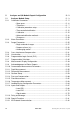
.2 5.2.1 5.2.2 5.3 6 6.1 I/O Module Controls SIO Module DIO Module(s) I/O Module Setup 5 -83 5 -84 5 -93 5 -99 6.2 6.3 6.4 6.5 6.6 System Configuration 6- 1 Diagnostic Menus........................................................................................... 6 - 3 6.1.1 Control Module Diagnostics................................................................. 6 - 4 6.1.2 Analyzer Module Diagnostics .............................................................. 6 - 5 Date and Time................
IV NGA 2000 90003482(2) [NGA-e (MLT-Software 3.2.
1 Introduction This software manual describes step by step how to operate successfully with the ½ 19" and 19" MLT analyzer module and analyzer of the NGA 2000 Series. Chapter two shows the structure of the MLT software menus. Chapter three describes the display and the keyboard of the analyzer. Chapter four describes the basic controls with detailed illustrations. So you can easily compare the actual display of the analyzer module with the illustrations of the manual.
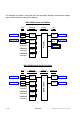
The following illustrations shall make plain the connection between the hardware configuration and the software setup of the modules: NGA 2000 System via Platform (see 5.1.18) (see 5.1.18) Analyzer Modules (AM's) SIO DIO SIO DIO Control Module (CM) I/O Modules TFID 1 SIO (see 5.2.1) MLT 4 DIO's max. (see 5.2.2) (additional manuals) CLD (additional manuals) PMD (additional manuals) FID Platform Local I/O's Other I/O's NGA 2000 System via MLT Analyzer (see 5.1.18) (see 5.1.
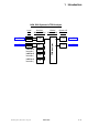
1 Introduction NGA 2000 System via TFID Analyzer (see 5.1.18) (see 5.1.18) Analyzer Modules (AM's) SIO DIO SIO DIO TFID MLT (additional manuals) CLD (additional manuals) PMD (additional manuals) FID 90003482(2) [NGA-e (MLT-Software 3.2.X)] 07/98 Control Module (CM) TFID Analyzer Local I/O's NGA 2000 System I/O Modules 1 SIO (see 5.2.1) 1 DIO (see 5.2.
1-4 NGA 2000 90003482(2) [NGA-e (MLT-Software 3.2.
90003482(2) [NGA-e (MLT-Software 3.2.X)] 07/98 Main Menu Section 3.8 NGA 2000 Analyzer and I/Omodule expert configuration... System configuration and diagnostics... Display controls... Section 4 Section 5 Section 6 Section 7 - Calibration procedure status... - Zero calibration of all ranges - Span calibration of the current range - Current gas valve setting: - Zero gas flow - Span gas flow - Sample gas flow - Test gas flow - Closing all valves - Analyzer module controls...
2-2 NGA 2000 90003482(2) [NGA-e (MLT-Software 3.2.
3 Startup and Operation, General Notes and Main Menu 3.1 Starting and Initializing After switching on the MLT analyzer or analyzer module (in a platform or part of a NGA network), the initialization procedure will be performed. A self control of the analyzer modules or the analyzer is running. You can see a sequence of several displays. They show the status of initialization, revision notes of the MLT software and the tag: (C) 1998 FISHER-ROSEMOUNT Analytical NGA-2000 Control Module/Version 3.2.
3.2 Display and Function The LCD screen shows all measurement values of the analyzer and all customer instructions. You can operate with five function keys, four arrow keys (cursors) and the enter key. The function of each key depends on: ♦ the type of analyzer/analyzer module used ♦ the optional auxiliary modules (e.g. I/O boards) used ♦ the individual menu displayed In case of power failure all customer specific module parameters are saved by a batterypowered buffer. 3.
3 Startup and Operation, General Notes and Main Menu 3.4 Lines and Softkey Functionality Lines can be selected by the ↓ -key or the ↑ -key. The selected line is displayed white on black. You have four different types of lines in the menu: Menu line... / Menu Softkey... ♦ Line/Softkey lettering ending with three dots. ♦ You will go to a submenu/further menu by pressing the softkey resp. by pressing the 8 -key or the → -key in the menu line.
Text Line TAG 37.50 ppm -- Calibration Procedure Status -Procedure status: Ready Remaining procedure time: 0 s Current/expected gas flow: Samplegas Concentration in span gas units: 37.50 ppm ---------------------- Results ---------------------Last zero calibration: Success Last span calibration: Success Last zero calibration was: Fri 05-29-1998 13:32:06 Last span calibration was: Fri 05-29-1998 13:37:23 Successful zero+span calibrated ranges: 1+2+3+4 Measure F1 Cancel ! F2 Back...
3 Startup and Operation, General Notes and Main Menu Lock ♦ Lock of all three operation levels from the main menu, if a security code is activated in the system configuration level (see section 6.3 p. 6-7). ♦ F4 in the main menu. Calib (see section 4.4 p. 4-37 and 5.1.1 p. 5-15!) ♦ Change from the single component display to the menu "Analyzer module calibration". ♦ F5 in the single component display. MFG Data (see section 3.8 p.
3.7 Starting a function If you press the 8 -key or the → -key in a function line, you will be asked to confirm the order in the following way: 37.50 ppm TAG -- Confirmation Required -Do you really want to do this ?? Press "Yes" or "Back..." Yes F1 F2 Back... F3 F4 F5 ♦ If you will press the F2 key, the function will start immediately. ♦ If you will press the F4 key, you will go back to the last menu page.
3 Startup and Operation, General Notes and Main Menu 3.8 Main Menu If you press the F3 key (Main...) or the → -key in any single component display, you will change to the "Main Menu".
Ramifications from the menu "Module Manufacturing Data": 1. Control module data: TAG TAG 95.00 ppm 95.00 ppm -- Module Manufacturing Data -Control module data... Analyzer module data... (C) Copyright Fisher-Rosemount GmbH & Co, 1998 Manufactured by: Fisher-Rosemount GmbH & Co Industriestrasse 1 D-63594 Hasselroth / Germany Tel. (+49) 6055 884-0 FAX. (+49) 6055 884-209 Measure F1 <<< F2 F3 Back... Measure >>> F4 F1 F5 TAG 95.00 ppm Or... F2 F3 Back... More... F4 F5 TAG 95.
4 Basic Controls and Analyzer Module Calibration In the chapter "Basic Controls and Analyzer Module Calibration" the most important measurement and calibration functions of your MLT analyzer or analyzer module are described. All steps are figured with detailed illustrations and operation instructions. In the left column you can see display and keyboard of the NGA front panel. The keys you have to press are illustrated in black. In the right column you can read the instructions and notes.
4-2 NGA 2000 90003482(2) [NGA-e (MLT-Software 3.2.
4.1 Analyzer Channel Status TAG 37.50 ppm CH4 ⇒ Change to the menu "Analyzer Channel Status" F2 Range: 1 0.00 Failures: No Maintenance-Requests: No Temperature: 20.0 C 0.0 Operation: Ready Display F1 Status... F2 Main... F3 Press 50.00 100.0 Channel F4 Calib... F5 37.50 ppm TAG -- Analyzer Channel Status -Status details... Operational settings... RawMeas F1 F2 F1 164 Ready No No No No No Channel F3 Back...
4-4 NGA 2000 90003482(2) [NGA-e (MLT-Software 3.2.
4.1.1 Analyzer Channel Status - Status Details Failures TAG 37.50 ppm CH4 Range: 1 0.00 Display F1 Status... Main... F2 F3 F2 50.00 Failures: No Maintenance-Requests: No Temperature: 20.0 C 0.0 Operation: Ready ⇒ Change to the menu "Analyzer Channel Status" Press 100.0 Channel F4 Calib... F5 37.50 ppm TAG -- Analyzer Channel Status -- ⇒ Change to the submenu "Status Details" Status details... Operational settings...
MLT25/CH2/R2 37.50 ppm ⇒ Change to the second menu page -- List of Possible Failures(1/2) -One or more failures: Configuration replaced by factory setting: Chopper fail: Raw signal too high: Detector signal communication failed: Raw signal too low: (reserved) (reserved) Temperature measurement: Invalid pressure measurement: Measure F1 No No No No No No No No Back... F2 F3 More... F4 F5 37.
4.1.1 Analyzer Channel Status - Status Details Maintenance Requests TAG 37.50 ppm CH4 Range: 1 0.00 Display F1 Status... F2 Main... F3 F2 50.00 Failures: No Maintenance-Requests: No Temperature: 20.0 C 0.0 Operation: Ready ⇒ Change to the menu "Analyzer Channel Status" Press 100.0 Channel F4 Calib... F5 37.50 ppm TAG -- Analyzer Channel Status -- ⇒ Change to the submenu "Status Details" Status details... Operational settings...
TAG 37.50 ppm -- Status Details -Failures... Maintenance requests... Function controls... Measurements/Alarms... Events... Press Acknowledge and clear failures ! Acknowledge and clear maintenance requests ! Acknowledge and clear function controls ! Measure F1 or Back... F2 F3 F4 F5 37.
4.1.1 Analyzer Channel Status - Status Details Maintenance Requests TAG 37.50 ppm CH4 Range: 1 0.00 50.00 Failures: No Maintenance-Requests: No Temperature: 20.0 C 0.0 Operation: Ready Display F1 Status... F2 Main... F3 90003482(2) [NGA-e (MLT-Software 3.2.X)] 07/98 ⇒ Back in the single component display of the current channel 100.0 Channel F4 Calib...
4 - 10 NGA 2000 90003482(2) [NGA-e (MLT-Software 3.2.
4.1.1 Analyzer Channel Status - Status Details Function Controls TAG 37.50 ppm CH4 Range: 1 0.00 Display F1 Status... F2 Main... F3 F2 50.00 Failures: No Maintenance-Requests: No Temperature: 20.0 C 0.0 Operation: Ready ⇒ Change to the menu "Analyzer Channel Status" Press 100.0 Channel F4 Calib... F5 37.50 ppm TAG -- Analyzer Channel Status -- ⇒ Change to the submenu "Status Details" Status details... Operational settings...
TAG 37.50 ppm -- Status Details -Failures... Maintenance requests... Function controls... Measurements/Alarms... Events... Press Acknowledge and clear failures ! Acknowledge and clear maintenance requests ! Acknowledge and clear function controls ! Measure F1 or Back... F2 F3 F4 F5 37.
4.1.1 Analyzer Channel Status - Status Details Measurements/Alarms TAG 37.50 ppm CH4 Range: 1 0.00 Display F1 Status... F2 Main... F3 F2 50.00 Failures: No Maintenance-Requests: No Temperature: 20.0 C 0.0 Operation: Ready ⇒ Change to the menu "Analyzer Channel Status" Press 100.0 Channel F4 Calib... F5 37.50 ppm TAG -- Analyzer Channel Status -- ⇒ Change to the submenu "Status Details" Status details... Operational settings...
TAG 37.50 ppm -- Status Details -Failures... Maintenance requests... Function controls... Measurements/Alarms... Events... Press Acknowledge and clear failures ! Acknowledge and clear maintenance requests ! Acknowledge and clear function controls ! Measure F1 ⇒ Change to the submenu "Measurements/ Alarms" or Back... F2 F3 F4 F5 TAG 37.50 ppm ⇒ Change to the single component display -- Measurements/Alarms -- F1 Press Concentration... Concentration average... Flow... Pressure...
4.1.1 Analyzer Channel Status - Status Details Events TAG 37.50 ppm CH4 Range: 1 0.00 Display F1 Status... F2 Main... F3 F2 50.00 Failures: No Maintenance-Requests: No Temperature: 20.0 C 0.0 Operation: Ready ⇒ Change to the menu "Analyzer Channel Status" Press 100.0 Channel F4 TAG Calib... F5 37.50 ppm -- Analyzer Channel Status -- ⇒ Change to the submenu "Status Details" Status details... Operational settings...
TAG 37.50 ppm -- Status Details -Failures... Maintenance requests... Function controls... Measurements/Alarms... Events... ⇒ Change to the submenu "Analyzer Module Events (page 1 of 2)" Press Acknowledge and clear failures ! Acknowledge and clear maintenance requests ! Acknowledge and clear function controls ! or Measure F1 Back... F2 F3 F4 MLT25/CH2/R2 F5 37.
4.1.1 Analyzer Channel Status - Status Details Events TAG 37.50 ppm CH4 Range: 1 0.00 50.00 Failures: No Maintenance-Requests: No Temperature: 20.0 C 0.0 Operation: Ready Display F1 Status... F2 Main... F3 90003482(2) [NGA-e (MLT-Software 3.2.X)] 07/98 ⇒ Back to the single component display of the current channel 100.0 Channel F4 Calib...
4 - 18 NGA 2000 90003482(2) [NGA-e (MLT-Software 3.2.
4.1.1 Analyzer Channel Status - Status Details Acknowledge and Clear Failures TAG 37.50 ppm CH4 Range: 1 0.00 Display F1 Status... F2 Main... F3 F2 50.00 Failures: Yes Maintenance-Requests: No Temperature: 20.0 C 0.0 Operation: Ready Press 100.0 Channel F4 TAG ⇒ Change to the menu "Analyzer Channel Status" Calib... F5 37.50 ppm -- Analyzer Channel Status -- Notes: If you have solved the reasons for the failures reported, you should start this function.
⇒ Start the function TAG 37.50 ppm -- Status Details -- Press Failures... Maintenance requests... Function controls... Measurements/Alarms... Events... or Acknowledge and clear failures ! Acknowledge and clear maintenance requests ! Acknowledge and clear function controls ! Measure F1 Back... F2 F3 F4 F5 Note: Starting this function here is only possible, if it is enabled in the menu "Acknowledgement of Status Reports" (see 5.1.9 p. 5-52) ! ⇒ Confirm the order TAG 37.
4.1.1 Analyzer Channel Status - Status Details Acknowledge and Clear Failures TAG 37.50 ppm -- Status Details -Failures... Maintenance requests... Function controls... Measurements/Alarms... Events... ⇒ Change to the single component display of the channel selected F1 Press Acknowledge and clear failures ! Acknowledge and clear maintenance requests ! Acknowledge and clear function controls ! Measure F1 Back... F2 F3 F4 F5 TAG 37.50 ppm CH4 Range: 1 0.00 50.
4 - 22 NGA 2000 90003482(2) [NGA-e (MLT-Software 3.2.
4.1.1 Analyzer Channel Status - Status Details Acknowledge and Clear Maintenance Requests TAG 37.50 ppm CH4 Range: 1 0.00 Display F1 Status... F2 Main... F3 F2 50.00 Failures: No Maintenance-Requests: Yes Temperature: 20.0 C 0.0 Operation: Ready Press 100.0 Channel F4 TAG ⇒ Change to the menu "Analyzer Channel Status" Calib... F5 37.50 ppm -- Analyzer Channel Status -- Note: If you have solved the reasons for the maintenance requests reported, you should start this function.
⇒ Start the function TAG 37.50 ppm -- Status Details -- Press Failures... Maintenance requests... Function controls... Measurements/Alarms... Events... or Acknowledge and clear failures ! Acknowledge and clear maintenance requests ! Acknowledge and clear function controls ! Measure F1 Back... F2 F3 F4 F5 Note: Starting this function here is only possible, if it is enabled in the menu "Acknowledgement of Status Reports" (see 5.1.9 p. 5-52) ! ⇒ Confirm the order TAG 37.
4.1.1 Analyzer Channel Status - Status Details Acknowledge and Clear Maintenance Requests TAG 37.50 ppm -- Status Details -Failures... Maintenance requests... Function controls... Measurements/Alarms... Events... ⇒ Change to the single component display of the channel selected F1 Press Acknowledge and clear failures ! Acknowledge and clear maintenance requests ! Acknowledge and clear function controls ! Measure F1 Back... F2 F3 F4 F5 TAG 37.50 ppm CH4 Range: 1 0.00 50.
4 - 26 NGA 2000 90003482(2) [NGA-e (MLT-Software 3.2.
4.1.1 Analyzer Channel Status - Status Details Acknowledge and Clear Function Controls TAG 37.50 ppm CH4 Range: 1 0.00 Display F1 Status... F2 Main... F3 F2 50.00 Failures: No Maintenance-Requests: No Temperature: 20.0 C 0.0 Operation: Ready Press 100.0 Channel F4 Calib... F5 37.50 ppm TAG ⇒ Change to the menu "Analyzer Channel Status" -- Analyzer Channel Status -- Notes: If you have solved the reasons for the function controls reported, you should start this function.
⇒ Start the function TAG 37.50 ppm -- Status Details -- Press Failures... Maintenance requests... Function controls... Measurements/Alarms... Events... or Acknowledge and clear failures ! Acknowledge and clear maintenance requests ! Acknowledge and clear function controls ! Measure F1 Back... F2 F3 F4 F5 Note: Starting this function here is only possible, if it is enabled in the menu "Acknowledgement of Status Reports" (see 5.1.9 p. 5-52) ! ⇒ Confirm the order 37.
4.1.1 Analyzer Channel Status - Status Details Acknowledge and Clear Function Controls TAG 37.50 ppm -- Status Details -Failures... Maintenance requests... Function controls... Measurements/Alarms... Events... ⇒ Change to the single component display of the channel selected F1 Press Acknowledge and clear failures ! Acknowledge and clear maintenance requests ! Acknowledge and clear function controls ! Measure F1 Back... F2 F3 F4 F5 TAG 37.50 ppm CH4 Range: 1 0.00 50.
4 - 30 NGA 2000 90003482(2) [NGA-e (MLT-Software 3.2.
4.1.2 Analyzer Channel Status - Operational Settings TAG 37.50 ppm CH4 Range: 1 0.00 Display F1 Status... F2 Main... F3 F2 50.00 Failures: No Maintenance-Requests: No Temperature: 20.0 C 0.0 Operation: Ready ⇒ Change to the menu "Analyzer Channel Status" Press 100.0 Channel F4 Calib... F5 37.50 ppm TAG -- Analyzer Channel Status -- ⇒ Change to the line "Operational settings..." Status details... Operational settings...
TAG 37.50 ppm -- Analyzer Operation Settings -Remote control: Range change control: Range: Range upper limit: Span gas concentration: t90-time: Hours of operation: Last re-start occured: Actual zero gas concentration: Auto-start procedures... Measure F1 Enabled Manual 1 50.00 ppm 50.00 ppm 2.00 s 164 8:40:35 June 22, 1998 0.00 ppm Channel F2 F4 F5 37.
4.2 Single Component Display Change of Channel MLT25/CH1/R2 2.50 %CO2 Range: 2 0 Display Status... F1 F2 Main... F3 F4 5.00 Temperature: 25.0 C 0.0 Maintenance-Requests: No Any_Alarms: No Operation: Ready Press 100.0 Channel F4 F5 ppm CO Range: 2 0 250 Temperature: 25.0 C 0.0 Maintenance-Requests: No Any_Alarms: No Operation: Ready Display F1 Status... F2 Main... F3 Channel F4 Calib... F5 MLT25/CH1/R2 %CO2 Range: 2 0 F1 Status... F2 Main...
4 - 34 NGA 2000 90003482(2) [NGA-e (MLT-Software 3.2.
4.3 Multi Component Display Change of Channel ⇒ Change to the multi component display MLT25/CH1/R2 2.50 %CO2 Range: 2 0 Temperature: 25.0 C 0.0 Maintenance-Requests: No Any_Alarms: No Operation: Ready Display F1 Status... F2 Press 100.0 Main... Channel F3 F1 5.00 F4 Calib... Note: You can change to the multi component display from each single component display. F5 ⇒ Enable the "selecting symbol": > MLT25/CH1 %CO2 MLT25/CH2 ppm CO MLT25/CH3 ppm SO2 MLT25/CH4 ppm NO MLT25/CH5 %O2 2.50 95.
MLT25/CH1 %CO2 MLT25/CH2 ppm CO MLT25/CH3 ppm SO2 MLT25/CH4 ppm NO MLT25/CH5 %O2 2.50 95.00 333.0 150.0 20.00 Select Status... F1 F2 0.00 [2] 5.00 0.00 [2] 250.00 [2] 0.00 [2] F.S. 150.00 0.00 [2] 0.00 Tags Off F3 500.00 100.00 LCDReset F4 ppm CO Range: 2 0 F1 4 - 36 Status... F2 Main... F3 Note: With the F5 key you can enable the LCD-brightness and contrast of the factory settings (see also section 7).
4.4 Calibration Procedure Status TAG 37.50 ppm CH4 Range: 1 0.00 Display F1 Status... F2 Main... F3 F5 50.00 Failures: No Maintenance-Requests: No Temperature: 20.0 C 0.0 Operation: Ready Press 100.0 Channel F4 Calib... F5 37.50 ppm TAG -- Analyzer Module Calibration -Calibration procedure status... Start zero calibration procedure ! Start span calibration procedure ! Time & Date: Valve position: Expected zero gas: Expected span gas: Span gas name: Measure F1 Status... F2 F3 Back.
TAG 37.50 ppm -- Calibration Deviations -Deviation from zero: Sum of zero deviations: 0.34 ppm 4.41 ppm Deviation from span: Sum of span deviations: Measure F1 0.82 ppm 7.57 ppm Channel F2 F3 Back... F4 F5 37.50 Options: • With the F3 key you can change to further available channels to check their "Calibration Deviations". • With the F4 key you can go back to the menu "Calibration Procedure Status". ppm CH4 Range: 1 0.00 50.00 Failures: No Maintenance-Requests: No Temperature: 20.0 C 0.
4.5 Zero Calibration TAG 37.50 ppm CH4 ⇒ Change to the menu "Analyzer Module Calibration" F5 Range: 1 0.00 Caution: Failures: No Maintenance-Requests: No Temperature: 20.0 C 0.0 Operation: Ready Display F1 Status... F2 Main... F3 Press 50.00 100.0 Channel F4 Calib... F5 37.50 ppm TAG -- Analyzer Module Calibration -Calibration procedure status...
TAG 37.50 ppm ⇒ Confirm the order for zero calibration F2 Press to start the zeroing immediately. -- Confirmation Required -Do you really want to do this ?? Press "Yes" or "Back..." Yes F1 F2 Back... F3 F4 F5 37.50 ppm TAG Option: Press the F4 key if you want to cancel the order. Notes: • The display of this message depends on the setup in the expert configurations. (see 5.1.8 p. 5-49) • The 3 following illustrations show the displays you can see after starting the zeroing procedure.
4.5 Zero Calibration TAG 0.00 ppm -- Calibration Procedure Status -Procedure status: Ready Remaining procedure time: 0 s Current/expected gas flow: Samplegas Concentration in span gas units: 0.00 ppm ---------------------- Results ---------------------Last zero calibration: Success Last span calibration: Success Last zero calibration was: Mon 06-08-1998 09:21:34 Last span calibration was: Fri 05-29-1998 13:37:23 Successful zero+span calibrated ranges: 1+2+3+4 Measure F1 Cancel ! F2 Back... F3 More.
4 - 42 NGA 2000 90003482(2) [NGA-e (MLT-Software 3.2.
4.6 Span Calibration TAG 37.50 ppm CH4 Range: 1 0.00 Display F1 Status... F2 Main... F3 F5 50.00 Failures: No Maintenance-Requests: No Temperature: 20.0 C 0.0 Operation: Ready Press Caution: 100.0 Channel F4 Calib... F5 37.50 ppm TAG -- Analyzer Module Calibration -Calibration procedure status... Start zero calibration procedure ! Start span calibration procedure ! Time & Date: Valve position: Expected zero gas: Expected span gas: Span gas name: Measure F1 Status...
TAG 37.50 ppm ⇒ Confirm the order for span calibration F2 Press to start the spanning immediately. -- Confirmation Required -- Option: Press the F4 key if you want to cancel the order. Notes: • The display of this message depends on the setup in the expert configurations. (see 5.1.8 p. 5-49) • The 3 following illustrations show the displays you can see after starting the spanning procedure. Do you really want to do this ?? Press "Yes" or "Back..." Yes F1 F2 Back... F3 F4 TAG F5 37.
4.6 Span Calibration TAG 50.00 ppm -- Calibration Procedure Status -Procedure status: Ready Remaining procedure time: 0 s Current/expected gas flow: Samplegas Concentration in span gas units: 50.00 ppm ---------------------- Results ---------------------Last zero calibration: Success Last span calibration: Success Last zero calibration was: Mon 06-08-1998 09:21:34 Last span calibration was: Mon 06-08-1998 09:28:13 Successful zero+span calibrated ranges: 1+2+3+4 Measure F1 Cancel ! F2 Back...
4 - 46 NGA 2000 90003482(2) [NGA-e (MLT-Software 3.2.
4.7 Flow Zero Gas TAG 37.50 ppm CH4 Range: 1 0.00 Display F1 Status... F2 Main... F3 F5 50.00 Failures: No Maintenance-Requests: No Temperature: 20.0 C 0.0 Operation: Ready Press Caution: 100.0 Channel F4 Calib... F5 37.50 ppm TAG -- Analyzer Module Calibration -Calibration procedure status... Start zero calibration procedure ! Start span calibration procedure ! Time & Date: Valve position: Expected zero gas: Expected span gas: Span gas name: Measure F1 Status...
TAG 37.50 ppm ⇒ Confirm the order to flow zero gas F2 Press to start the zero gas flow immediately. -- Confirmation Required -Do you really want to do this ?? Press "Yes" or "Back..." Yes F1 Back... F2 F3 F4 TAG F5 37.50 ppm -SUCCESS- The selected function has been started/executed (Wait a moment...) F1 F2 F3 F4 TAG 0.
4.7 Flow Zero Gas TAG 0.00 ppm CH4 Range: 1 0.00 50.00 Failures: No Maintenance-Requests: No Temperature: 20.0 C 0.0 Operation: Ready Display F1 Status... F2 Main... F3 90003482(2) [NGA-e (MLT-Software 3.2.X)] 07/98 ⇒ Single component display appears during the zero gas flow is running 100.0 Channel F4 Calib...
4 - 50 NGA 2000 90003482(2) [NGA-e (MLT-Software 3.2.
4.8 Flow Span Gas TAG 37.50 ppm CH4 Range: 1 0.00 Display F1 Status... F2 Main... F3 F5 50.00 Failures: No Maintenance-Requests: No Temperature: 20.0 C 0.0 Operation: Ready Press Caution: 100.0 Channel F4 Calib... F5 37.50 ppm TAG -- Analyzer Module Calibration -Calibration procedure status... Start zero calibration procedure ! Start span calibration procedure ! Time & Date: Valve position: Expected zero gas: Expected span gas: Span gas name: Measure F1 Status...
TAG 37.50 ppm ⇒ Start the span gas flow -- Set Gas Valves -Flow zero gas ! Flow span gas ! Flow sample gas ! Flow test gas ! Press Close all valves ! or Valve position: Operation status: Measure F1 Samplegas Ready Status... F2 Channel F3 Back... F4 F5 37.50 ppm TAG Starting this function will switch on the span gas valve as current gas valve. ⇒ Confirm the order to flow span gas F2 Press to start the span gas flow immediately.
4.8 Flow Span Gas TAG 50.00 ppm -- Set Gas Valves -Flow zero gas ! Flow span gas ! Flow sample gas ! Flow test gas ! Close all valves ! Valve position: Operation status: Measure F1 Status... F2 Spangas-1 Ready Channel F3 Back... F4 F5 TAG 50.00 ppm CH4 Range: 1 F.S. 0.00 F1 Status... F2 Main... F3 90003482(2) [NGA-e (MLT-Software 3.2.X)] 07/98 Options: • Start the gasflow with zero gas, sample gas or test gas. • Close all valves.
4 - 54 NGA 2000 90003482(2) [NGA-e (MLT-Software 3.2.
4.9 Flow Sample Gas TAG 0.00 ppm CH4 Range: 1 0.00 Display F1 Status... F2 Main... F3 F5 50.00 Failures: No Maintenance-Requests: No Temperature: 20.0 C 0.0 Operation: Ready Press 100.0 Channel F4 Calib... F5 0.00 ppm TAG -- Analyzer Module Calibration -Calibration procedure status... Start zero calibration procedure ! Start span calibration procedure ! Time & Date: Valve position: Expected zero gas: Expected span gas: Span gas name: Measure F1 Status...
TAG 0.00 ppm ⇒ Start the sample gas flow -- Set Gas Valves -Flow zero gas ! Flow span gas ! Flow sample gas ! Flow test gas ! Press Close all valves ! or Valve position: Operation status: Measure F1 Zerogas Ready Status... F2 Channel F3 Back... F4 F5 0.00 ppm TAG Starting this function will switch on the sample gas valve as current gas valve. ⇒ Confirm the order to flow sample gas F2 Press to start the sample gas flow immediately.
4.9 Flow Sample Gas TAG 37.50 ppm -- Set Gas Valves -Flow zero gas ! Flow span gas ! Flow sample gas ! Flow test gas ! Close all valves ! Valve position: Operation status: Measure F1 Status... F2 Samplegas Ready Channel F3 Back... F4 F5 TAG 37.50 ppm CH4 Range: 1 0.00 F1 Status... F2 Main... F3 90003482(2) [NGA-e (MLT-Software 3.2.X)] 07/98 Options: • Start the gasflow with zero gas, span gas or test gas. • Close all valves.
4 - 58 NGA 2000 90003482(2) [NGA-e (MLT-Software 3.2.
4.10 Flow Test Gas TAG 37.50 ppm CH4 Range: 1 0.00 Display F1 Status... F2 Main... F3 F5 50.00 Failures: No Maintenance-Requests: No Temperature: 20.0 C 0.0 Operation: Ready Press 100.0 Channel F4 F5 -- Analyzer Module Calibration -Calibration procedure status... Start zero calibration procedure ! Start span calibration procedure ! Time & Date: Valve position: Expected zero gas: Expected span gas: Span gas name: Measure F1 Status...
TAG 37.50 ppm ⇒ Start the function to flow test gas -- Set Gas Valves -Flow zero gas ! Flow span gas ! Flow sample gas ! Flow test gas ! Press Close all valves ! or Valve position: Operation status: Measure F1 Samplegas Ready Status... F2 Channel F3 Back... F4 F5 37.50 ppm TAG ⇒ Confirm the order to flow test gas F2 Press to start the test gas flow immediately. -- Confirmation Required -Do you really want to do this ?? Press "Yes" or "Back..." Yes F1 F2 Back... F3 F4 TAG F5 37.
4.10 Flow Test Gas TAG 20.00 ppm -- Set Gas Valves -Flow zero gas ! Flow span gas ! Flow sample gas ! Flow test gas ! Close all valves ! Valve position: Operation status: Measure F1 Status... F2 Testgas Ready Channel F3 Back... F4 F5 TAG 20.00 ppm CH4 Range: 1 0.00 F1 Status... F2 Main... F3 90003482(2) [NGA-e (MLT-Software 3.2.X)] 07/98 Options: • Start the gasflow with zero gas, span gas or sample gas. • Close all valves.
4 - 62 NGA 2000 90003482(2) [NGA-e (MLT-Software 3.2.
4.11 Close all Valves TAG 37.50 ppm CH4 Range: 1 0.00 Display F1 Status... F2 Main... F3 F5 50.00 Failures: No Maintenance-Requests: No Temperature: 20.0 C 0.0 Operation: Ready Press 100.0 Channel F4 Calib... F5 37.50 ppm TAG -- Analyzer Module Calibration -Calibration procedure status... Start zero calibration procedure ! Start span calibration procedure ! Time & Date: Valve position: Expected zero gas: Expected span gas: Span gas name: Measure F1 Status...
TAG 37.50 ppm ⇒ Start the function to close all valves -- Set Gas Valves -Flow zero gas ! Flow span gas ! Flow sample gas ! Flow test gas ! Press Close all valves ! or Valve position: Operation status: Measure F1 Samplegas Ready Status... F2 Channel F3 Back... F4 F5 37.50 ppm TAG ⇒ Confirm the order to close all valves F2 Press to close all valves immediately. -- Confirmation Required -Do you really want to do this ?? Press "Yes" or "Back..." Yes F1 F2 Back... F3 F4 TAG F5 37.
4.11 Close all Valves TAG 37.50 ppm ⇒ Change to the single component display of the current channel AllClosed Ready Options: • Start the gasflow with zero gas, span gas, sample gas or test gas. • F3 key: Changing to another available channel to execute gas flow. • F4 key: Go back to the menu "Analyzer Module Calibration" to start zeroing or spanning.
4 - 66 NGA 2000 90003482(2) [NGA-e (MLT-Software 3.2.
5 Analyzer and I/O-Module Expert Configuration If you press the 8 -key or the → -key in the line "Analyzer and I/O-module expert configuration..." of the "Main Menu", you will change to the following display: TAG 37.50 ppm -- Expert Module Configuration -Analyzer module controls... I/O module controls... Analyzer module setup... I/O module setup... Measure F1 Channel F2 F3 Back...
Structure of chapter five: At the begin of any chapter you will find the way to a certain submenu of the MLT software starting from the line "Analyzer and I/O-module expert configuration" in the "Main Menu". The way will be described with the software catchwords, that you have to enter one after another to reach the corresponding submenu. At the end of the catchword listing you will find the illustration of the LCD screen. After that you can read the set up instructions and explanations.
5.1 Analyzer Module Setup Main Menu — Analyzer and I/O-module expert configuration ↓ Analyzer module setup ↓ 95.00 ppm TAG -- Analyzer Module Setup and Controls (1/3) -Calibration parameters... Alarm parameters... Range parameters... Cross interference compensation... Linearization... Programmable logic control (PLC)... Programmable calculator... Measurement display configuration... Acknowledgement of status reports... Concentration measurement parameters... Measure ManData F1 F2 Channel F3 Back.
From the menu "Analyzer Module Setup and Controls" you can change to all menus and submenus of the expert configuration level via the corresponding menu lines. Changing to the menus and submenus: ♦ Select the menu line you want with the ↓ -key or the ↑ -key. If necessary: Change to a further menu page with the F5 key (More...) ♦ Change to the corresponding menu/submenu with the 8 -key or the → -key.
5.1 Analyzer Module Setup 5.1.1 Calibration Parameters Main Menu — Analyzer and I/O-module expert configuration ↓ Analyzer module setup ↓ Calibration parameters ↓ TAG 37.50 ppm -- Calibration Parameters -Span gases... Tolerances... Calibration procedure setup... Time controlled calibration... Calibration... Advanced calibration methods... Zero gases... Measure F1 Channel F2 F3 Back...
5.1 Analyzer Module Setup 5.1.1 Calibration Parameters – Span gases Main Menu — Analyzer and I/O-module expert configuration ↓ Analyzer module setup ↓ Calibration parameters ↓ Span gases ↓ MLT25/CH2/R2 95.00 ppm -- Span Gas Definition -Actual span gas concentration: Spangas range -1: Spangas range -2: Spangas range -3: Spangas range -4: 250.0 50.00 250.0 2500 10000 Span gas unit: ppm "ppm" --> "mg/Nm3" conversion factor: Concentration in span gas units: Measure F1 ppm ppm ppm ppm ppm 1.000 95.
5.1 Analyzer Module Setup 5.1.1 Calibration Parameters – Tolerances Main Menu — Analyzer and I/O-module expert configuration ↓ Analyzer module setup ↓ Calibration parameters ↓ Tolerances ↓ TAG 95.00 ppm -- Tolerances -Max. zero calibration deviation: Max. span calibration deviation: Check deviation: Stability tolerance - range 1: Stability tolerance - range 2: Stability tolerance - range 3: Stability tolerance - range 4: 20.00 % 20.00 % Disabled 100.00 % 100.00 % 100.00 % 100.
Lines of variables "Max. zero calibration deviation" / "Max. span calibration deviation": The deviation between two zero or span gas concentrations will be determined during the stability time of the calibration procedure (see menu "Calibration Procedure Setup" p. 5-9/10). The maximum calibration deviation is the deviation tolerance expressed as percentage of the current end of range value. The calibration procedure will only be possible within this range.
5.1 Analyzer Module Setup 5.1.1 Calibration Parameters – Calibration procedure setup Main Menu — Analyzer and I/O-module expert configuration ↓ Analyzer module setup ↓ Calibration parameters ↓ Calibration procedure setup ↓ TAG 95.00 ppm -- Calibration Procedure Setup -Purge time: Procedure times-out after: Analog output during calibration: Span ranges: 10 s 120 s Tracking Together Valve position: Samplegas Stability time: Averaging time: 30 s 5 s Measure F1 Channel F2 F3 Back...
If the deviation of the two values is less then the allowed maximum calibration deviation (see menu "Tolerances", p. 5-7/8), the calibration may start. If not, the stability control is starting again until a stable measurement is possible. The time in the line "Procedure times-out after" is the limit for the whole procedure.
5.1 Analyzer Module Setup 5.1.1 Calibration Parameters – Calibration procedure setup Line of variables "Span ranges": ♦ Together: All measurement ranges of the same channel will be calibrated together. This is the usual calibration mode. ♦ Separately: Each measurement range will be calibrated separately. Line of variables "Valve position": Options: ♦ Samplegas ♦ Zerogas ♦ Purgegas ♦ Testgas ♦ Spangas-1...-4 ♦ Linearizer ♦ Spangas ♦ AllClosed ♦ Other-Proc.
5.1 Analyzer Module Setup 5.1.1 Calibration Parameters – Time controlled calibration Main Menu — Analyzer and I/O-module expert configuration ↓ Analyzer module setup ↓ Calibration parameters ↓ Time controlled calibration ↓ TAG 37.50 ppm -- Time Control -Zero calibration - Day of week: - Hour: - Minute: Span calibration - Day of week: - Hour: - Minute: Zero+Span calibration - Day of week: - Hour: - Minute: Measure F1 Channel F2 F3 Never 0 0 Never 0 0 Never 0 0 Back... F4 ShowList...
Further Parameters: Via the F5 key (ShowList) you can change to the following submenu: TAG 37.50 ppm -- Auto-Start Procedures -Position in auto-start list: 1 Erase current position from list ! Erase all positions from list ! Channel tag: Procedure type: Interval mode: Start time: Start date: Never - Measure F1 Back... F2 F3 F4 F5 In this submenu you can determine some further parameters of the time controlled calibration.
5 - 14 NGA 2000 90003482(2) [NGA-e (MLT-Software 3.2.
5.1 Analyzer Module Setup 5.1.1 Calibration Parameters – Calibration Main Menu — Analyzer and I/O-module expert configuration ↓ Analyzer module setup ↓ Calibration parameters ↓ Calibration ↓ TAG 37.50 ppm -- Analyzer Module Calibration -Calibration procedure status... Start zero calibration procedure ! Start span calibration procedure ! Time & Date: Valve position: Expected zero gas: Expected span gas: Span gas name: Measure F1 Status... F2 12:50:55 June 16, 1998 Samplegas 0.00 ppm 50.
Via the F5 key you can change to the menu "Set Gas Valves", where you can ♦ set up the gas flow of the current channel with • • • • • zero gas or span gas or sample gas or test gas or close all valves. Starting the functions: ♦ Change to the line you want with the ↑ -key or the ↓ -key. 8 -key or the → -key or cancel and go back to the last menu page with the F4 key (Back...) or the ← -key.
5.1 Analyzer Module Setup 5.1.1 Calibration Parameters – Calibration Menu "Calibration Procedure Status": Press the 8 -key or the → -key in the line "Calibration procedure status..." to change to the corresponding submenu: TAG 37.50 ppm -- Calibration Procedure Status -Procedure status: Ready Remaining procedure time: 0 s Current/expected gas flow: Samplegas Concentration in span gas units: 37.
5.1 Analyzer Module Setup 5.1.1 Calibration Parameters – Advanced calibration methods Main Menu — Analyzer and I/O-module expert configuration ↓ Analyzer module setup ↓ Calibration parameters ↓ Advanced calibration methods ↓ TAG 95.
Notes: ♦ The signal has to be stable before starting any calibration ! ♦ If you want to start the zero and the span calibration separately, or if you want to calibrate separately each channel of an MLT analyzer/analyzer module, or if you want to calibrate the measurement ranges separately with span gas, you have to change to the menu "Analyzer Module Calibration" (see p. 5-15) resp. to the menu "Calibration Procedure Setup" (p.5-9).
5.1 Analyzer Module Setup 5.1.1 Calibration Parameters – Zero Gases Main Menu — Analyzer and I/O-module expert configuration ↓ Analyzer module setup ↓ Calibration parameters ↓ Zero gases ↓ TAG 37.50 ppm -- Zero Gas Definition -Zero gas concentration (all ranges): Measure F1 0.00 ppm Back... F2 F3 F4 F5 In the menu "Zero Gas Definition" you can set up the zero gas concentration for all ranges of the current channel of an MLT analyzer or analyzer module.
5.1 Analyzer Module Setup 5.1.2 Alarm Parameters Main Menu — Analyzer and I/O-module expert configuration ↓ Analyzer module setup ↓ Alarm parameters ↓ TAG 95.00 ppm -- Alarms Setup (1/2) -Alarm delay: 0.2 s Concentration... Concentration average... Flow... Pressure... Temperature... Acknowledge alarms ! Measure F1 Status... F2 Back... F3 F4 TAG More... F5 95.00 ppm -- Alarms Setup (2/2) -- Calculator-1... Calculator-2... Calculator-3... Calculator-4... Measure F1 Status... F2 Back...
Parameters set up or changing to submenus: ♦ Select the line of variables, any menu line or the function line with the ↓ -key or the ↑ -key. ♦ Select the variable, start the function or change to the submenu with the 8 -key or the → -key. ♦ Select any digit with the ← -key or the → -key and adjust a new value with the ↑ -key or the ↓ -key resp. select the whole parameter with the ↑ -key or the ↓ -key. 8 -key or cancel and go back to the last value with the F2 key.
5.1 Analyzer Module Setup 5.1.2 Alarm Parameters Alarms Setup and Control – Example: Concentration Alarm Setup ♦ Select the parameter you want in the menu "Alarms Setup", i.e. "Concentration", and change to the corresponding menu: Note: If the setup of the parameter selected is not possible, a corresponding message will appear on the screen, i.e. no flow sensor installed to measure the flow. 95.
On: The alarm message of the signal parameter selected will only appear as long as the signal will exceed the allowed level. The alarm message will disappear, if the value is again in the range allowed. • On (Hold Alarm): The alarm message for the signal parameter selected will appear after the signal will have exceeded the allowed value. The alarm message will also keep alive, if the value will be back again in the range allowed.
5.1 Analyzer Module Setup 5.1.3 Range parameters Main Menu — Analyzer and I/O-module expert configuration ↓ Analyzer module setup ↓ Range parameters ↓ TAG 95.00 ppm -- Range parameters -Begin and end of ranges... Response times (t90)... Autoranging control... Range control: Actual range number: Measure F1 Manual 1 Channel F2 F3 Back...
♦ Manual: You have to change the range manual. The switch level hysteresis is disabled (see p. 5-30). ♦ Self/Automatic: The autoranging is running by the comparison of the current measure- ment value with the end of range. The signal at the analog output is tracking. The value in the line "Switch level hysteresis" of the menu "Autoranging Control" is enabled (see p. 5-30). ♦ Program I/O-module: The autoranging is controlled by the I/O-Board.
5.1 Analyzer Module Setup 5.1.3 Range parameters – Begin and end of ranges Main Menu — Analyzer and I/O-module expert configuration ↓ Analyzer module setup ↓ Range parameters ↓ Begin and end of ranges ↓ TAG 95.00 ppm -- Begin and End of Ranges -Begin of range -1: Begin of range -2: Begin of range -3: Begin of range -4: End of range -1: End of range -2: End of range -3: End of range -4: Actual begin of range: Actual end of range: Measure F1 0.00 0.00 0.00 0.00 50.00 250.0 2500 10000 0.00 250.
5.1 Analyzer Module Setup 5.1.3 Range parameters – Response times (t90) Main Menu — Analyzer and I/O-module expert configuration ↓ Analyzer module setup ↓ Range parameters ↓ Response times (t90) ↓ TAG 95.00 ppm -- Response Times -Range -1: Range -2: Range -3: Range -4: 2.00 2.00 2.00 2.00 Actual range number: t90-time: 1 2.00 s Measure F1 Channel F2 F3 s s s s Back... F4 F5 In the menu "Response Times" you can set up the response time (t90-time) for each range of the current channel.
5.1 Analyzer Module Setup 5.1.3 Range parameters – Autoranging control Main Menu — Analyzer and I/O-module expert configuration ↓ Analyzer module setup ↓ Range parameters ↓ Autoranging control ↓ TAG 95.00 ppm -- Autoranging Control -Switch level hysteresis: Usage of range -1: Usage of range -2: Usage of range -3: Usage of range -4: 10 % Enabled Enabled Enabled Enabled Absolute, range lower limit: Absolute, range upper limit: Calculate switch levels automatically: Measure F1 Channel F2 F3 0.
Notes: ♦ You can enable or disable each range in the lines "Usage of range -1, ..., -4". ♦ "Range -4" has not to be the biggest range. Set up parameters: ♦ Select any line of variables with the ↓ -key or the ↑ -key. ♦ Select the variable with the 8 -key or the → -key. ♦ Select any digit with the ← -key or the → -key and adjust a new value with the ↑ -key or the ↓ -key resp. select the whole parameter with the ↑ -key or the ↓ -key.
5.1 Analyzer Module Setup 5.1.4 Cross Interference Compensation Main Menu — Analyzer and I/O-module expert configuration ↓ Analyzer module setup ↓ Cross interference compensation ↓ TAG 95.00 ppm -- Cross Interference Compensation -Compensation is: Disabled Selected interference component: 1 Choose interference source channel... Interference factors... Calculate factor for selected interference component ! Remove selected component ! 1. Interference component: 2. Interference component: 3.
• You can repeat the last two steps as often as necessary until you have selected all interference components (maximum 3) you need. MLT25/CH2/R2 95.00 ppm -- Channels -- MLT25/CH2 MLT25/CH3 MLT25/CH5 Measure F1 Back... F2 F3 F4 F5 4) Give the interference component into the sample gas channel and wait for a stable signal. 5) Go to the line "Calculate factor for selected interference component !" with the ↑ -key or the ↓ -key and then start the calculation with the 8 -key or the → -key.
5.1 Analyzer Module Setup 5.1.5 Linearization Main Menu — Analyzer and I/O-module expert configuration ↓ Analyzer module setup ↓ Linearization ↓ TAG 95.00 ppm -- Linearization -Linearization Procedure... Linearization raw values... Linearization setpoint values... Set all raw/setpoint values to 0.0 ! Calculate linearization curve coefficients... Linearization is: Measure F1 Disabled Channel F2 F3 Back... F4 Info... F5 95.
Conditions: ♦ Before you start the linearization you have to calibrate the largest range of the channel (usually range 4) with zero gas and span gas. ♦ You have to record a raw values/setpoint values table to linearize a channel. You need minimum 6 raw values and their corresponding setpoint values: zero, end of range and 4 intermediate values. You should take 10 to 15 values (maximum: 30) to improve the precision of the linearization curve.
5.1 Analyzer Module Setup 5.1.5 Linearization Change with the ↓ -key to the next line to put in the second value. Repeat these steps until all raw/setpoint values of the table are part of the corresponding menus. • If you have more than 10 values you can go to further menu pages with the F5 key (More...). There are maximum 30 lines available. The current menu page number is always displayed in the headline.
5) Calculate linearization curve: • Change in the menu "Linearization" to the menu line "Calculate linearization curve coefficients..." with the ↑ -key or the ↓ -key. • Press the 8 -key or the → -key to change to the corresponding submenu: TAG 3163.860 ppm Used method: All ranges ** Unused x/y-pairs must be set to 0.0 ** Start calculation for used method ! Used x/y-pairs: Used method: Splines Measure F1 • • • • • Back...
5.1 Analyzer Module Setup 5.1.6 Programmable Locic Control (PLC) Main Menu — Analyzer and I/O-module expert configuration ↓ Analyzer module setup ↓ Programmable logic control (PLC) ↓ TAG 95.00 ppm -- Programmable Logic Control -Programming... Disabled Measure F1 Back... F2 F4 In the menu "Programmable Logic Control" you can enable or disable the logic control of the MLT analyzer, of the analyzer module or of the digital outputs by a corresponding program.
Programming ( + Consider the example p. 5-41 to 5-43 !): 1) Disable PLC: • Before you will begin with the programming you have to disable the PLC function in the line "PLC is" to avoid starting the program while you are writing it. 2) Put in the program: • Press the 8 -key or the → -key in the line "Programming..." to change to the submenu, where you can put in your program step by step (+ See example p. 5-42). • A program is composed of single commands (e.g.
5.1 Analyzer Module Setup 5.1.
Measurement-Channels Signal ID Ch 1 Signal ID Ch 2 Signal ID Ch 3 Signal ID Ch 4 Signal ID Ch 5 110 111 112 113 114 115 116 117 118 119 120 121 122 123 124 125 126 127 128 129 130 131 132 133 134 135 136 137 138 139 140 141 142 143 144 145 146 147 148 149 150 151 152 153 154 155 156 157 158 159 160 161 162 163 164 165 166 167 168 169 170 171 172 173 174 175 176 177 178 179 180 181 182 183 184 185 186 187 188 189 190 191 192 193 194 195 196 197 198 199 200 201 202 203 204 205 206 207 208 209 210 211 2
5.1 Analyzer Module Setup 5.1.6 Programmable Locic Control (PLC) Example for PLC Programming: ♦ You have three channels in your analyzer: CO, SO2 and O2. ♦ You want to write a program for the zero and span gas calibration.
You have to put in the codes of the table into the corresponding lines of the submenu "Program". If you have more than ten program steps, you can change to another menu page with the F5 key(More...). Maximum of program steps: 100. Maximum of results: 20. Putting in the codes in the menu: ♦ Select the program steps with the ↑ -key or the ↓ -key. ♦ Select the field for the code number with the 8 -key or the → -key.
5.1 Analyzer Module Setup 5.1.6 Programmable Locic Control (PLC) Start the program with "Enabled" in the line "PLC is" of the menu "Programmable Logic Control". Then, control the output status in the submenu "PLC Outputs". You will reach this menu via the line "Results..." in the menu "Programmable Logic Control": TAG 0.00 ppm -- PLC Outputs -Out -1: Out -2: Out -3: Out -4: Out -5: Out -6: Out -7: Out -8: Out -9: Out -10: On Off Off Off Off Off Off Off Off Off Measure F1 Back... F2 F3 F4 More...
5 - 44 NGA 2000 90003482(2) [NGA-e (MLT-Software 3.2.
5.1 Analyzer Module Setup 5.1.7 Programmable Calculator Main Menu — Analyzer and I/O-module expert configuration ↓ Analyzer module setup ↓ Programmable calculator ↓ TAG 95.00 ppm -- Programmable Calculator -Programming... Constants... Units... Calculator is: Scaling... Enabled Result Calculator 1: Result Calculator 2: Result Calculator 3: Result Calculator 4: 0.012 Vol% 123.000 ppm _ _ Measure F1 Back...
In the following table you can see which types of operators and operands you can use: Operator types -1 -2 -3 -4 -5 -6 -7 -8 -9 -10 -11 -12 -13 -14 -15 -16 -17 Operand Types 1 2 3 4 5 6 7 8 9 10 11 12 13 14 15 16 17 18 19 20 21 22 23 24 25 26 27 28 29 5 - 46 Operator Description Add Operand to IR (intermediate result) ADD Subtract Operand from IR SUB Divide IR by operand DIV Multiply IR with operand MUL Add Constant to IR ADDC c Subtract constant from IR SUBC c Divide IR by constant DIVC c Multiply IR wit
5.1 Analyzer Module Setup 5.1.7 Programmable Calculator • You have to set each operator in the line above the corresponding variable. After each calculating step you have to store the intermediate result and to delete the memory before you will continue with the next step. Each program must end with the command "End of program". 3) Putting in the constants: • Press the 8 -key or the → -key in the line "Constants...
You have to put in the codes of the table into the corresponding lines of the submenu "Program". If the program consists of more than ten steps, you can change to another menu page with the F5 key. Maximum of program steps: 100. Maximum of results: 4 Maximum of constants: 4. Putting the program steps in the menu: ♦ Select the program steps with the ↑ -key or the ↓ -key. ♦ Select the field for the code number with the 8 -key or the → -key.
5.1 Analyzer Module Setup 5.1.8 Measurement Display Configuration Main Menu — Analyzer and I/O-module expert configuration ↓ Analyzer module setup ↓ Measurement display configuration ↓ TAG 95.
Line of variables "Displayed concentration digits": ♦ You can adjust the number of digits for the concentration display. Options: 3, 4, 5, 6 Line of variables "Digits after decimal point": ♦ Options: 0, 1, 2, 3 Line of variables "Display confirmation menus": ♦ Yes: After each function start you will be asked "Do you really want to do this ?". So you will have the option to cancel the order for function start or to confirm it. ♦ No: You will never be asked to cancel or confirm any function.
5.1 Analyzer Module Setup 5.1.8 Measurement Display Configuration "Tags...": Via the F5 key (Tags...) you can change to the second page of the menu "Measurement Display Configuration". There you can adjust the identification tag of the MLT analyzer or analyzer module and the tag of each range for the current channel. These range tags will appear at the top left of each menu page display. If you want to change the tags of the other channels, you have to press the F3 key.
5.1 Analyzer Module Setup 5.1.9 Acknowledgement of Status Reports Main Menu — Analyzer and I/O-module expert configuration ↓ Analyzer module setup ↓ Acknowledgement of status reports ↓ TAG 95.
• • • • • Failures Maintenance requests Function controls Measurements/Alarms Events and the operational settings of the current channel like • • range settings and response time (t90-time). The menu "Analyzer Channel Status" and its submenus are displayed detailed in section 4.1. Set up parameters: ♦ Select the line of variables or any function line with the ↓ -key or the ↑ -key. ♦ Select the variable or start the function with the 8 -key or the → -key.
5.1 Analyzer Module Setup 5.1.10 Concentration Measurement Parameters Main Menu — Analyzer and I/O-module expert configuration ↓ Analyzer module setup ↓ Concentration measurement parameters ↓ MLT25/CH2/R2 95.00 ppm -- General Concentration Measurement Setup -Sample gas unit: ppm "ppm" --> "mg/Nm3" conversion factor: Lower explosion limit (LEL): Upper explosion limit (UEL): 1.000 10.00 % 20.00 % Measurement output during failure: Measure F1 Actual Back...
5.1 Analyzer Module Setup 5.1.11 Concentration Peak Measurement Main Menu — Analyzer and I/O-module expert configuration ↓ Analyzer module setup ↓ [2nd menu page via F5 (More...)] Peak measurement ↓ TAG 95.00 ppm -- Concentration Peak Measurement -Reset minimum ! Reset maximum ! Reset both ! Minimum detection: Maximum detection: Always Always Difference (Max-Min): Last minimum: Last maximum: 2.500 93.400 95.900 Measure F1 Channel F2 F3 Back...
Lines of variables "Minimum detection" or "Maximum detection": ♦ Always: The minimum or the maximum detection is running automatically. ♦ External: The minimum or the maximum detection depends on an external instruction. ♦ Off: No detection of the extreme values is running. Lines of variables "Difference (Max-Min), "Maximum", "Minimum": ♦ These lines display the actual or last minimum/maximum value and the difference of the extreme values for one channel of an MLT analyzer or analyzer module.
5.1 Analyzer Module Setup 5.1.12 Differential Measurement Main Menu — Analyzer and I/O-module expert configuration ↓ Analyzer module setup ↓ [2nd menu page via F5 (More...)] Differential measurement ↓ TAG 95.00 ppm -- Differential Measurement -Function is: Choose source channel... Source concentration: Store source concentration ! Disabled Use actual value Source channel: Measure F1 ---Channel F2 F3 Back...
MLT25/CH2/R2 95.00 ppm -- Channels -- MLT25/CH1 MLT25/CH2 MLT25/CH3 MLT25/CH4 MLT25/CH5 Measure F1 Back... F2 F3 F4 F5 Change to the line you want with the ↓ -key or the ↑ -key. • Select the tag of the reference channel with the 8 -key or the → -key: The display will go back to the menu "Differential Measurement" automatically. You can see the channel selected in the line "Source channel".
5.1 Analyzer Module Setup 5.1.13 Gasflow Setup Main Menu — Analyzer and I/O-module expert configuration ↓ Analyzer module setup ↓ [2nd menu page via F5 (More...)] Gasflow setup ↓ TAG 95.00 ppm -- Gasflow Setup -Gasflow through analyzer cell is: Parallel Valve position at "Basic-Status": Samplegas Valve position: Operation status: Samplegas Ready Measure F1 Channel F2 F3 Back...
5.1 Analyzer Module Setup 5.1.14 Pressure Compensation Main Menu — Analyzer and I/O-module expert configuration ↓ Analyzer module setup ↓ [2nd menu page via F5 (More...)] Pressure compensation ↓ TAG 95.00 ppm -- Pressure Compensation -Compensation: Manual pressure: Unit: Use manual pressure 1013.0 hPa hPa Pressure measurement is: Reference pressure: Pressure: Measure F1 Valid 1013.0 hPa 1013.0 hPa Channel F2 F3 Back...
Line of variables "Manual pressure": ♦ You can put in the actual atmospheric pressure which can be used for pressure compensation. ♦ Potential values: 500 to 1300 hPa resp. 7,3 to 18,9 psig Line of variables "Unit": ♦ You can set up the pressure unit for the pressure compensation. ♦ Options: • • hPa psig Lines of variables "Pressure measurement is", "Reference pressure", "Pressure": These lines are information lines. They are not available. 90003482(2) [NGA-e (MLT-Software 3.2.
5.1 Analyzer Module Setup 5.1.15 Flow Measurement Main Menu — Analyzer and I/O-module expert configuration ↓ Analyzer module setup ↓ [2nd menu page via F5 (More...)] Flow measurement ↓ TAG 95.00 ppm -- Flow Measurement -Unit: ml/min Flow measurement is: Flow: Valid 23.0 ml/min Measure F1 Back... F2 F3 F4 F5 In the menu "Flow Measurement" you can set up the flow unit for the current channel of an MLT analyzer or analyzer module.
5.1 Analyzer Module Setup 5.1.16 Temperature Measurement Main Menu — Analyzer and I/O-module expert configuration ↓ Analyzer module setup ↓ [2nd menu page via F5 (More...)] Temperature measurement ↓ TAG 95.00 ppm -- Temperature Measurement -Unit: F Temperature measurement is: Temperature: Valid 77.0 F Measure F1 Back... F2 F3 F4 F5 In the menu "Temperature Measurement" you can set up the temperature unit for the current channel of an MLT analyzer or analyzer module.
5.1 Analyzer Module Setup 5.1.17 Load/Save Analyzer Module Configuration Main Menu — Analyzer and I/O-module expert configuration ↓ Analyzer module setup ↓ [2nd menu page via F5 (More...)] Loading/saving configuration parameters ↓ TAG 95.00 ppm -- Load/Save Analyzer Module Configuration -Send configuration to serial interface ! Load configuration from serial interface ! Reset analyzer module...
Menu line "Reset analyzer module...": ♦ Change to the line "Reset analyzer module..." with the ↑ -key or the ↓ -key. ♦ Press the 8 -key or the → -key to change to the corresponding submenu: TAG 95.00 ppm -- Reset Analyzer Module -- Microprocessor RESET ! Measure F1 ♦ Press the Back... F2 F3 F4 F5 8 -key or the → -key to start the function. If asked, confirm with the F2 key (Yes) or cancel and go back to the menu page with the F4 key (Back...) or the ← -key.
5 - 66 NGA 2000 90003482(2) [NGA-e (MLT-Software 3.2.
5.1 Analyzer Module Setup 5.1.18 Inputs and Outputs (Local SIO/DIO) Main Menu — Analyzer and I/O-module expert configuration ↓ Analyzer module setup ↓ [2nd menu page via F5 (More...)] Inputs and outputs ↓ TAG 95.00 ppm -- Analyzer Module I/O-Modules -SIO-01 module... DIO-module(s)... Measure F1 <<< F2 F3 Back...
5.1 Analyzer Module Setup 5.1.18 Inputs and Outputs – Local SIO Main Menu — Analyzer and I/O-module expert configuration ↓ Analyzer module setup ↓ [2nd menu page via F5 (More...)] Inputs and outputs ↓ SIO-01 module ↓ TAG 95.00 ppm -- Local SIO Configuration Parameters -Analog output setup... Serial interface setup... Configuration of Relay Outputs... Module installed: Enabled Measure F1 Back...
Analog Output Setup: Press the 8 -key or the → -key in the line "Analog output setup..." to change to the corresponding submenu: TAG 95.00 ppm -- Analog Outputs -Output number: Choose analyzer module... Signal name: Signal value for 0% output: Signal value for 100% output: Output current range: Use range limits for concentration scaling: Analyzer module: Signal value: Output Voltage: Measure F1 1 Concentration 0.00 250.00 0...20 mA Enabled MLT25/CH1 95.00 3.8 V Back... F2 F3 F4 More...
Go to the line you want with the ↑ -key or the ↓ -key. • Select the tag of the channel with the 8 -key or the → -key: The display will go back to the menu "Analog Outputs" automatically. The tag of the channel selected will appear in the line "Analyzer module".
5.1 Analyzer Module Setup 5.1.18 Inputs and Outputs – Local SIO 5) Determination of the output current range: • Press the 8 -key or the → -key in the line "Output current range" to select the range and select the value you want with the ↑ -key or the ↓ -key. • Confirm the new adjustment with the 8 -key. • Options: 0...20 mA (and automatically 0...10V) or 4...20 mA (2...10V).
Serial interface setup: Press the 8 -key or the → -key in the line "Serial interface setup..." of the menu "Local SIO Configuration Parameters" to change to the corresponding submenu: TAG 95.00 ppm -- Serial Interface --Baudrate: Data bits: Stop bits: Parity: Echo mode: Handshake: Transmission delay: Type of installed serial interface: Communication protocol: Special protocol definitions... Measure F1 19200 8 1 None Disabled Xon/Xoff 0 RS232 AK Back...
5.1 Analyzer Module Setup 5.1.18 Inputs and Outputs – Local SIO Configuration of Relay Outputs: Press the 8 -key or the → -key in the line "Configuration of Relay Outputs..." of the menu "Local SIO Configuration Parameters" to change to the corresponding menu: TAG 95.00 ppm -- Relay Outputs -Relay 1 - output signal: Relay 2 - output signal: Relay 3 - output signal: 4 5 6 Relay 1 - actual state: Relay 2 - actual state: Relay 3 - actual state: On Off Off Measure F1 Back...
5.1 Analyzer Module Setup 5.1.18 Inputs and Outputs – Local DIO Main Menu — Analyzer and I/O-module expert configuration ↓ Analyzer module setup ↓ [2nd menu page via F5 (More...)] Inputs and outputs ↓ DIO-module(s) ↓ TAG 95.
Function line "Reset output fail !" The 24 digital outputs are composed of 3 units with 8 outputs. If there is a short circuit or an overload in one unit, it will be switched off and saved against destruction. After the defect is removed, the board is available immediately. You only have to press the 8 -key or the → -key in the line "Reset output fail !". If asked: Confirm with F2 key (Yes). Informations about the whole specification of the DIO board you will find in another manual.
Programmable Logic Controls Signal ID 40 41 42 43 44 45 46 47 48 49 50 51 52 53 54 55 56 57 58 59 60 61 -69 Signal Output Result buffer #1 Output Result buffer #2 Output Result buffer #3 Output Result buffer #4 Output Result buffer #5 Output Result buffer #6 Output Result buffer #7 Output Result buffer #8 Output Result buffer #9 Output Result buffer #10 Output Result buffer #11 Output Result buffer #12 Output Result buffer #13 Output Result buffer #14 Output Result buffer #15 Output Result buffer #16 Outpu
5.1 Analyzer Module Setup 5.1.
Function Codes 1 - 599 Available for: ♦ DIO inputs (see p. 5-74) The following functions occur only if the signal at the input changes from low to high level: ID 1 2 - 99 ID CH1 100 101 102 103 104 105 106 107 108 109 110 111 112 113 114 115 116 117 118 ... 149 General functions Set all channels into STANDBY state (Stop procedures) Reserved ID CH2 200 201 202 203 204 205 206 207 208 209 210 211 212 213 214 215 216 217 218 ...
5.1 Analyzer Module Setup 5.1.19 Delay and Average Main Menu — Analyzer and I/O-module expert configuration ↓ Analyzer module setup ↓ [2nd menu page via F5 (More...)] Delay and average ↓ TAG 95.00 ppm -- Delay and Average -Concentration output delay time: Delay function is: 1.000 s Disabled Averaging time: Set average to 0.0 ! 2 min Concentration average: Measure F1 93.87 ppm Channel F2 F3 Back...
Lines of variables "Concentration output delay time" / "Delay function is": ♦ With the setup in the line "Concentration output delay time", you can shift the absolute time of the analog output signal for one channel. If you use the right output delay time, you can watch the signals of several channels at the same starting time. ♦ Options: 0.000 to 3.000 seconds. ♦ Select "Enabled" in the line "Delay function is" to use the delay time for the concentration output. Example: Conc.
5.1 Analyzer Module Setup 5.1.20 Special Functions Main Menu — Analyzer and I/O-module expert configuration ↓ Analyzer module setup ↓ [2nd menu page via F5 (More...)] Special functions ↓ MLT25/CH2/R2 95.00 ppm -SORRY- - No special functions available - Back... F1 F2 F3 F4 F5 The menu "Special Functions" is reserved for functions of the typical measurement process for a certain analyzer module (e.g. CLD, FID, MLT-AM) ! 90003482(2) [NGA-e (MLT-Software 3.2.
5.1 Analyzer Module Setup 5.1.21 AK-Protocol Communication Main Menu — Analyzer and I/O-module expert configuration ↓ Analyzer module setup ↓ [3rd menu page via 2 times F5 (More...)] AK-protocol communication ↓ TAG 95.
5.2 I/O Module Controls Main Menu — Analyzer and I/O-module expert configuration ↓ I/O module controls ↓ TAG 95.00 ppm -- I/O Module Controls -SIO module... DIO module(s)... Measure F1 <<< F2 F3 Back... F4 >>> F5 From the menu "I/O Module Controls" you can change to some submenus where you can set up the parameters for the SIO module and the DIO modules of the MLT analyzer or platform: 8 -key or the → -key in the line "SIO module..." or in the line "DIO module(s)...
5.2 I/O Module Controls 5.2.1 SIO Module Main Menu — Analyzer and I/O-module expert configuration ↓ I/O module controls ↓ SIO module ↓ TAG 95.00 ppm -- SIO-Configuration Parameters -Analog output setup... Serial interface setup... Configuration of Relay Outputs... Module installed: Yes Measure F1 Back... F2 F3 F4 F5 From the menu "SIO - Configuration Parameters" you can change to submenus to control and set up several output configurations of the auxiliary SIO module.
5.2 I/O Module Controls 5.2.1 SIO Module – Analog output setup Analog Output Setup: Press the 8 -key or the → -key in the line "Analog output setup..." to change to the corresponding submenu: TAG 95.00 ppm -- Analog Outputs -Output number: Choose signal source module... Choose signal... Signal value for 0% output: Signal value for 100% output: Output current range: Hold output during calibration? Signal name: Current signal value: Source module: Measure F1 1 0.00 ppm 2500.00 ppm 0...
Go to the line you want with the ↑ -key or the ↓ -key. • Select the tag of the channel with the 8 -key or the → -key: The display will go back to the menu "Analog Outputs" automatically. The tag of the channel selected will appear in the line "Source module". • 3) Select any signal: • Change to the line "Choose signal" with the ↓ -key. • Press the 8 -key or the → -key to change to the submenu "Signals": TAG 95.
5.2 I/O Module Controls 5.2.1 SIO Module – Analog output setup 4) Determination of the output signal values: • You can determine the signal value for the 0% output and the 100% output in the lines "Signal value for 0% output" or "Signal value for 100% output". So you have the possibility to zoom out a certain part of the whole range.
7) Fine adjustment of the analog output: • If you press the F5 key in the menu "Analog Outputs" you can change to the submenu "Fine Adjustment", where you can do the fine adjustments of the analog output: TAG 95.00 ppm -- Fine Adjustment -Output number: 1 Operation mode: Fine adjustment for 0% output: Fine adjustment for 100% output: Measure F1 • Updates F2 Normal 4097 799 Back... F3 F4 F5 In the line "Output number" appears the output number selected in the menu "Analog Outputs".
5.2 I/O Module Controls 5.2.1 SIO Module – Serial interface setup Serial interface setup: Press the 8 -key or the → -key in the line "Serial interface setup..." of the menu "SIO Configuration Parameters" to change to the corresponding submenu: TAG 95.00 ppm -- Serial Interface --Baudrate: Data bits: Stop bits: Parity: Echo mode: Handshake: Transmission delay: Type of installed serial interface: Communication protocol: Special protocol definitions...
5.2 I/O Module Controls 5.2.1 SIO Module – Configuration of relay outputs Configuration of Relay Outputs: Press the 8 -key or the → -key in the line "Configuration of Relay Outputs..." of the menu "SIO - Configuration Parameters" to change to the corresponding menu: TAG 95.00 ppm -- Relay Outputs -Outputnumber: Invert signal: Choose source module... Choose signal... 1 Disabled Signal comes from: Signal name: Actual state: Control Module Function control ON Measure F1 Back...
MLT25/CH2/R2 95.00 ppm -- Analyzer Modules -- Control Module MLT25/CH1 MLT25/CH2 MLT25/CH3 MLT25/CH4 MLT25/CH5 Measure F1 <<< F2 Back... F3 F4 >>> F5 3) Select any signal: • Change to the line "Choose signal..." with the ↓ -key. • Press the 8 -key or the → -key to change to the submenu "Signals": TAG 95.00 ppm -- Signals -- Function control Maintenance request Failure Cal. in progress Zero in progress Span in progress Zero failed Span failed Measure F1 • <<< F2 F3 Back...
4) Invert signal: • You can decide, if the measurement signal should be inverted at the relay output. This can be necessary to combine a failure with an alarm control. Press the 8 -key or the → -key in the line "Invert signal" to select the parameter and adjust "Enabled" or "Disabled" with the ↑ -key or the ↓ -key. „ Confirm the parameter selected with the 8 -key or the → -key.
5.2 I/O Module Controls 5.2.2 DIO Module(s) Main Menu — Analyzer and I/O-module expert configuration ↓ I/O module controls ↓ DIO module(s) ↓ TAG 95.00 ppm -- DIO-Module Outputs -Inputs... Outputnumber: Choose module... Choose signal... Invert output: Module status: Slot ID: Signal name: Signal level: Signal comes from: Measure F1 1 Disabled Normal 1 ???? Off ???? Next... F2 F3 Back...
The last five lines of variables in the menu "DIO-Module Outputs" only display some adjustments of the DIO output selected! They are not available: ♦ "Module status:" displays the status of the current DIO board. ♦ "Slot ID:" displays the tag number of the DIO board selected. ♦ "Signal name:" displays the signal selected for the current DIO output. ♦ "Signal level:" displays the status of the signal selected. ♦ "Signal comes from:" displays the source module selected for the current DIO output.
5.2 I/O Module Controls 5.2.2 DIO Module(s) – Input configuration • Select the tag of the module with the 8 -key or the → -key: The display will go back to the menu "DIO-Module Inputs" automatically. The tag of the module selected will appear in the line "Signal comes from". MLT25/CH2/R2 95.00 ppm -- Analyzer Modules -- Control Module MLT25/CH1 MLT25/CH2 MLT25/CH3 MLT25/CH4 MLT25/CH5 Measure F1 <<< F2 Back... F3 F4 >>> F5 3) Select any function: • Change to the line "Choose function...
CLD-AM: NOx „ External failure „ External maintenance „ and further functions, depending of the analyzer module selected. • Select the function with the 8 -key or the → -key: The display will go back to the menu "DIO-Module Inputs" automatically. The function selected will appear in the line "Signal name".
5.2 I/O Module Controls 5.2.2 DIO Module(s) – Output configuration Go to the line you want with the ↑ -key or the ↓ -key. If there are more than eight source modules available, you have to press the F5 key to go to another menu page. • Select the tag of the module with the 8 -key or the → -key: The display will go back to the menu "DIO-Module Outputs" automatically. The tag of the module selected will appear in the line "Signal comes from". • 3) Select any signal: • Change to the line "Choose signal...
5 - 98 NGA 2000 90003482(2) [NGA-e (MLT-Software 3.2.
5.3 I/O Module Setup Main Menu — Analyzer and I/O-module expert configuration ↓ I/O module setup ↓ TAG 95.00 ppm -- I/O Module Setup -- Parameter: 3 Measure F1 <<< F2 Back...
5 - 100 NGA 2000 90003482(2) [NGA-e (MLT-Software 3.2.
6 System Configuration and Diagnostics If you press the 8 -key or the → -key in the line "System configuration and diagnostics..." of the "Main Menu", you will change to the following display: TAG 37.50 ppm -- System Configuration -System calibration... Diagnostic menus... Date and time... Security codes... Network module binding... System Reset... System modules... System tag: Measure F1 Fisher-Rosemount Channel F2 F3 Back...
Structure of chapter six: The structure of chapter six is analogous to the structur of chapter five: At the begin of any chapter you will find the way to a certain submenu of the MLT software, starting from the line "System configuration and diagnostics..." in the "Main Menu". The way will be described with the software catchwords, that you have to enter one after another to reach the corresponding submenu. At the end of the catchword listing you will find the illustration of the LCD screen.
6.1 Diagnostic Menus Main Menu — System configuration and diagnostics ↓ Diagnostic menus ↓ TAG 37.50 ppm -- Diagnostic menus -Control module diagnostics... Analyzer module diagnostics... Measure F1 <<< F2 F3 Back... F4 >>> F5 From the menu "Diagnostic menus" you can change to submenus, where you will find software error messages of the control module or of the analyzer module. If need be, you can remove the error messages in these menus.
6.1 Diagnostic Menus 6.1.1 Control Module Diagnostics Main Menu — System configuration and diagnostics ↓ Diagnostic menus ↓ Control module diagnostics ↓ TAG 37.50 ppm -- Control Unit Diagnostics -Software error code (1 = no error): Last software error message: And: And: And: And: And: And: And: Edit to reset: Measure F1 1 Report Back... F2 F3 F4 Reset... F5 In the menu "Control Unit Diagnostics" you can find software error messages of the control module.
6.1 Diagnostic Menus 6.1.2 Analyzer Module Diagnostics Main Menu — System configuration and diagnostics ↓ Diagnostic menus ↓ Analyzer module diagnostics ↓ TAG 37.50 ppm -- Analyzer Module Diagnostics -Software error code (1 = no error): Last software error message: And: And: And: And: And: And: And: Edit to reset: Measure F1 1 Report Back... F2 F3 F4 F5 In the menu "Analyzer Module Diagnostics" you can find software error messages of the analyzer module.
6.2 Date and Time Main Menu — System configuration and diagnostics ↓ Date and time ↓ TAG 37.50 ppm -- Date and Time -Time display format (am/pm): 24 Hrs Minutes: Hours (1...24): Year: Day: Month: 0 12 1998 4 5 Network updating: Current time: Enabled 14:01:35 12 May 1998 Measure F1 Set ! F2 F3 Back... F4 F5 In the menu "Date and Time" you can set up the date and the time of the control module (platform or MLT analyzer).
6.3 Security Codes Main Menu — System configuration and diagnostics ↓ Security codes ↓ TAG 37.50 ppm -- Security Setup -Basic level security: Disabled Expert level security: Disabled System level security: Disabled Define basic level security PIN... Define expert level security PIN... Define system level security PIN... Measure F1 Back...
• Example: „ „ Security code shall be: 53412 You have to press the sequence: F5 F3 F4 F1 F2 TAG 37.50 ppm -- Define Basic Level Security PIN -Press five softkeys in any order to define the PIN. The actual PIN is represented by the order in which they are pressed, and shown numerically below. Press the left arrow key when you are done.
6.4 Network Module Binding Main Menu — System configuration and diagnostics ↓ Network module binding ↓ MLT25/CH2/R2 95.
2) Selecting the I/O module: • Change to the line you want with the ↑ -key or the ↓ -key. If there are more than eight unbound I/O modules available, you can change to another menu page with the F5 key (>>>). • Press the 8 -key or the → -key to select the tag of the I/O module: The display will go back to the menu "Module binding" automatically. • Repeat the steps 1) and 2) as often as necessary until all modules you want to bind will be selected.
6.5 System Reset Main Menu — System configuration and diagnostics ↓ System Reset ↓ TAG 37.50 ppm -- System Reset -- Are you sure ??? Re-initializing will destroy all the binds !!! System reset ! Re-initialize network ! Measure F1 Back...
6.6 System Modules Main Menu — System configuration and diagnostics ↓ System modules ↓ MLT25/CH2/R2 95.00 ppm -- Modules known by the Control Module -- MLT25/CH1 MLT25/CH2 MLT25/CH3 MLT25/CH4 MLT25/CH5 Measure F1 <<< F2 F3 Back... F4 >>> F5 In the menu "Modules known by the Control Module" you will find the tags of all modules combined with the platform or the MLT analyzer. If there are more than eight modules available, you can change to another menu page with the F5 key (>>>).
7 Display Controls Main Menu — Display controls ↓ TAG 37.50 ppm -- Display Controls -Brightness: Contrast: 74 % 23 % Switch automatically to "Measure" after: 10 Min Measure More... F1 Back... F2 F3 F4 TAG F5 37.50 ppm -- Front Panel Control -- Maximum total number of digits: Digits after the decimal point: 4 2 Measure F1 Back... F2 F3 F4 TAG More... F5 37.
In the menu "Display Controls" you can set up several display parameters of the front panel. With the F5 key (More...) you can change to the menu "Front Panel Control", where you can set up the number of digits for the display of the measurement values. These numbers do not alter the accuracy of measurement. From the menu "Front Panel Control" you can change via the F5 key to the menu "Auxiliary Lines".
7 Display Controls The menu "Front Panel Control" Set up the number of digits: ♦ Select one of the two lines of variables with the ↓ -key or the ↑ -key. ♦ Select the number with the 8 -key or the → -key. ♦ Select the digit with the ↑ -key or the ↓ -key. Options: Maximum total number of digits: 3, 4, 5, 6 Digits after the decimal point: 0, 1, 2, 3. 8 -key or cancel and go back to the last value with the F2 key. ♦ Confirm the new value with the Example: ♦ Measured number: 1.
MLT25/CH2/R2 95.00 ppm -- First Auxiliary Line Source -- MLT25/CH2 Measure F1 <<< F2 F3 Back... F4 >>> F5 ♦ Select the line you want with the ↑ -key or the ↓ -key. If there are more than eight modules available, you can change to another menu page with the F5 key. ♦ Press the 8 -key or the → -key to enable the module selected as line source: The display will go back to the menu "Auxiliary Lines", automatically. The selection will be done.
Index A AK Communication Protocol 5-72, 5-82,5-89 Alarms 4-13 acknowledgement 5-22 delay 5-22 setup 5-21...24 Analog Output(s) fine adjustment 5-71, 5-88 holding 5-9/10 setup 5-69...71, 5-85...88 tracking 5-9/10 with 3 alarms I/O module 1-1, 5-99 ,6-9 Analyzer 1-1...3, 3-1 Analyzer Channel Status 4-3, 5-16 Analyzer Module 1-1, 3-1 calibration 4-1, 5-15...19 data 3-5/8 diagnostics 6-5 events 4-15 I/O modules 5-67 reset 5-65 setup 5-3...
D G Date and Time 6-6 Gas flow 5-50, 5-59 Delay Time 5-80 Deviations 4-38, 5-8, 5-17 H Diagnostic(s) analyzer module 6-5 control module 6-4 menus 6-3 Hardware Configuration 3-8 Differential Measurement 5-57/58 DIO Module 1-1, 5-74, 5-93 function codes 5-78, 5-95 inputs 5-74, 5-94 outputs 5-74, 5-96 Display 3-1/2/4 confirmation menus 5-49 controls 7-1/2 measurement display config. 5-49 multi component 4-35 resolution 5-49/50, 7-1...
Index M P Main Menu 3-7 Peak Measurement 5-55/56 Maintenance Requests 4-7, 4-23, 5-52 Platform 1-1...3 Manual Pressure 5-60/61 Manufacturing Data 3-5/7/8 "ppm → mg/Nm3" conversion factor 5-6, 5-54 Measure 3-4 Pressure 5-60 Measurement(s) 4-13 differential 5-57 peak 5-55/56 Procedures, Auto-start 4-32, 5-13 Menu line 3-3 main 3-7 softkey 3-3 structure 2-1 Mini Bargraph 5-49/50 Programmable Calculator 5-45...48 Programmable Logic Control (PLC) 5-37...
System modules 6-12 reset 6-4, 6-11 tag 6-1 S Sample Gas flow 4-55 pressure 5-81 unit 5-54 Save/Load Analyzer Module Config. 5-64 T Tag channel 3-2 range 5-49/51 system 6-1 Security Codes 6-7 Sensor Value 5-60 Serial Interface load/send configuration 5-64 setup 5-72, 5-89 Temperature 5-63 Test Gas 4-59, 5-15/16 Signal codes 5-38...40, 5-75...77 on mini-bargraph 5-49/50 Time and Date 6-6 Time Controlled Calibration 5-12 Single Component Display 3-1, 4-33, 5-49 auxiliary lines 7-1...
NGA-2000 System Calibration NGA-2000 Software Manual Supplement: System Calibration NGA-Software Version 3.2.X 90003482(2) [NGA-e (MLT-Software 3.2.
NGA-2000 System Calibration Table of Contents 1 Introduction _____________________________________________________________________2 2 Valves for system calibration ________________________________________________________4 2.1 Assigning an output-port to a system valve ________________________________________________ 4 3 Operating System Calibration _______________________________________________________6 3.1 Set-up analyzer modules _______________________________________________________________ 7 3.
NGA-2000 System Calibration 1 Introduction In opposite to the possibility to zero and span each analyzer module (MLT channel) individually and independently from the others, System-Calibration (SYSCAL) allows to combine the calibration procedures of all into a common process. This is been achieved with a special assignment of the valves. The idea is not longer to require for each gas of each analyzer an own valve. Instead of we have a pool of valves.
NGA-2000 System Calibration 2 Valves for system calibration Before using the system calibration we have to put together the required valve pool. There are in principle three types of I/O modules supporting this: • DIO • SIO • [CVU - - 24 digital outputs / 8 digital inputs (max. 4 DIO modules per platform or 2 per MLT/TFID analyzer) - 3 digital outputs (max. 1 SIO module per CM) - 4 digital outputs (max. 4 modules per CM)] Software supports up to 32 system valves.
NGA-2000 System Calibration It is also possible to configure the DIO-outputs via LON-Variables (i.e. SLTA-adapter or AKprotocol). Therefore is the LON-variable "DIOOUT_ENTRYSIG" which corresponds to DIOOUTSIGC and evaluates enum-values of ST1NAME (enum-values 0..19), ST2NAME (enum-values 20..39) or ST3NAME (enum-values 40..59). For digital output we have to setup variables in following order. 1. 2. 3. 4. DIOSLOTIDC DIOOUTNUMC DIOOUTSRCC DIOOUT_ENTRYSIG SYS: VALVE-1 SYS: VALVE-2 . . .
NGA-2000 System Calibration 3 Operating System Calibration Because there are many possibilities how to use SYSCAL it must be configured through the Expert Operator. There we can find the menu „System Calibration“ from were we can do the required setups and start routines. System configuration and diagnostics... ↓ System calibration... ↓ System Calibration Calibration/Test procedures... Calibration Sequence Programming... Times for interval operation... Set-up analyzer modules...
NGA-2000 System Calibration 3.1 Set-up analyzer modules Before we can run any system calibration features we have to include the different analyzer modules (AM’s) into system calibration by setup needed parameters. Only after correct setting up, an AM is included into system calibration and only then it makes sense to go into the other menus. System configuration and diagnostics... ↓ System calibration... ↓ Set-up analyzer modules... ↓ Analyzer Set up Choose analyzer module....
NGA-2000 System Calibration Example for an NGA analyzer system: V1 AM1 (MLT ch.1) V2 AM4 V3 AM5 V 4 V 5 AM2 (MLT ch.2) AM3 (MLT ch.3) V 6 Calibration gas mixtures Appropriate assignment: SAMPLE-GAS ZERO-GAS SPANGAS-1 SPANGAS-2 SPANGAS-3 SPANGAS-4 Attention: AM1/Ch.1 V1 V4 V5 V5 V6 V6 AM2/Ch.2 V1 V4 V5 V5 V5 V5 AM3/Ch.
NGA-2000 System Calibration 3.2 Programming Calibration Sequences Beside the standard programs „zero calibration“ and „zero/span calibration“ it is possible to run the system calibration in an user definable order of up to 40 steps. The menu to set-up this feature looks as follows. System configuration and diagnostics... ↓ System calibration... ↓ Calibration sequence programming... ↓ -- Calibration Sequence Programming -Step #: 1 Calibration procedure type: ZERO-CAL Choose specific analyzer module...
NGA-2000 System Calibration For each step we have the choice to select a specific AM or to activate the step for all enabled AMs.
NGA-2000 System Calibration 3.3 Set-up general parameters One general parameter is "Calibration Procedures in Test-Mode". It is located in the menu "Calibration/Test procedures". System configuration and diagnostics... ↓ System calibration... ↓ Calibration/Test procedures... ↓ -- Calibration/Test Procedures -Start Zeroing all ranges! Start Zeroing and Spanning all ranges ! Start calibration program ! Cancel calibration! Calibration Procedures in Test-Mode: Test Procedures...
NGA-2000 System Calibration A further general parameter is "Timeout for Gastest". It is located in the menu "Test procedures". System configuration and diagnostics... ↓ System calibration... ↓ Calibration/Test Procedures... ↓ Test procedures... ↓ -- Test Procedures -Gastest of specific module Timeout for Gastest (0 = no timeout) Choose specific analyzer module...
NGA-2000 System Calibration 3.4 Controlling System Calibration After setting-up there is the possibility to start 3 different modes: system zero-calibration: In this mode a zero-cal of all modules, which are enabled for SYSCAL, will be performed. The order of modules depends on purge time for zero-valves because the whole calibration is time optimized. system zero/span-calibration: In this mode will be performed a zero-cal and a span-cal for every enabled AM.
NGA-2000 System Calibration 3.4.1 Control via menu system The possibility to control via menu is located in the menu page „Calibration/Test procedures“. There can be started and stopped any kind of system calibration respectively test procedure. System configuration and diagnostics... ↓ System Calibration... ↓ Calibration/Test procedures...
NGA-2000 System Calibration The result of calibration for included AMs is displayed in an own menu page. This can be achieved by softkey „Result...“ from different menu pages of SYSCAL. - Calibration Results Choose analyzer module...
NGA-2000 System Calibration Here we first choose the specific analyzer module and then we select at the parameter "Gastest of specific module" the required gas.
NGA-2000 System Calibration 3.4.2 Control System Calibration by LON-Variables SYSCAL can also be controlled by LON-Variable CMFUNC. Setting this variable will cause the appropriate function (see following table). CMFUNC 1 2 3 4 function which is started system zero-calibration system zero/span-calibration user defined sequence program cancel a running system calibration We can also realize some other functionality with setting of LON-Variables.
NGA-2000 System Calibration 3.4.3 Control System Calibration by Programmable Inputs We can use the possibility to control SYSCAL by triggering with programmable inputs. This feature is supported by inputs of the DIO-Module. Assigning of an programmable input can be accomplished by using the menus for DIO module. Analyzer and I/O-module expert configuration... ↓ I/O module controls... ↓ DIO module(s)... ↓ Inputs... ↓ -- DIO- Module Inputs -Inputnumber: Choose module... Choose function...
NGA-2000 System Calibration It is also possible to configure the DIO-inputs only per LON-Variables (i.e. SLTA-adapter or AK-protocol). Therefore is the LON-variable "DIOINP_ENTRYSIG" which corresponds to DIOINPSIGC and evaluates enum-values of STINAME. For each digital input we have to setup variables in following order. 1. 2. 3. 4. DIOSLOTIDC DIOINPNUMC DIOINPSRCC DIOINP_ENTRYSIG 90003482(2) [NGA-e (MLT-Software 3.2.
NGA-2000 System Calibration 3.4.4 Control System Calibration by AK-protocol command We can start and stop SYSCAL over serial interface by AK-protocol commands. Therefore the commands SCAL, STBY and ASTZ has to be used. Start-Command: SCAL Kx m (n) m (type of SYSCAL) 0 = ZERO-CAL 1 = ZERO/SPAN-CAL 2 = PROGRAM 3 = TEST ZERO-GAS 4 = TEST SPAN-GAS1 5 = TEST SPAN-GAS2 6 = TEST SPAN-GAS3 7 = TEST SPAN-GAS4 Kx (channel number) K0 K0 K0 K1...999 K1...999 K1...999 K1...999 K1...
NGA-2000 System Calibration 3.4.5 Time controlled System Calibration To activate a time controlled system calibration we have to set-up this in an own menu page. System configuration and diagnostics... ↓ System Calibration... ↓ Times for interval operation... ↓ -- Times for Interval Operation -Zero-Cal is: Start of interval time: Interval time: Zero/Span-Cal is: Start of interval time: Interval time: Program-Cal is: Start of interval time: Interval time: Next calibration events...
NGA-2000 System Calibration For example: • • • • • Starting time for zero calibration: daily at 2:00 o´clock. Starting time for zero/span calibration: weekly at 10:00 o´clock. Starting time for program calibration: weekly at 16.00 o´clock Entry in menu page „times for interval operation“ are at 4/13/99 at 8.00 o´clock First possible calibration: 4/14/99 at 2 o´clock (then all 24 hours automatically) We can display the calculated ACT-times in menu page „next calibration events“...
NGA-2000 System Calibration 3.5 Calibrate single Analyzers/ Analyzer Modules/ MLT Channels Each specific analyzer has still the possibility to start a calibration over other instances than SYSCAL. For this functionality we now have some additional considerations. • Do not start a calibration of a single AM or MLT channel during a running SYSCAL. This will confuse the valve switching and the calibration commands of SYSCAL. Therefore look also for all automatic start instances of an analyzer.
NGA-2000 System Calibration 4 Functionality 4.1 Gas flow The gas flow through the analyzers can be configured in any way: 1. only serial 2. only parallel 3. serial and parallel mixed Sample 1 V1 AM1 Sample 2 V2 AM4 Sample 3 V3 AM5 V 4 V 5 AM2 AM3 V 6 Calibration gas mixtures Connections for program logic and flow configurations: • To each AM (channel) must be assigned a sample gas valve.
NGA-2000 System Calibration 4.2 Running system calibration The system calibration is running in an own Task. This task is only allowed to run once. Any try to restart this task is refused. The main steps SYSCAL-Task has to do are realized in the following way. 1. 2. 3. 4. Fill all actions to do into a sequence buffer.
NGA-2000 System Calibration 4.2.1 Filling sequence buffer The contents of the sequence buffer depends on • calibration types and belonging module type • coherence of modules and system valves An evaluation procedure has the choice of listed action types.
NGA-2000 System Calibration Example of a filled sequence buffer Assignment of modules, system-valves and purge-times: SAMPLE-GAS ZERO-GAS SPANGAS-1 SPANGAS-2 SPANGAS-3 SPANGAS-4 AM1 V1 / 5 sec V4 / 10 sec V5 / 10 sec V5 / 10 sec V6 / 10 sec V6 / 10 sec AM2 V1 / 5 sec V4 / 10 sec V5 / 10 sec V5 / 10 sec V5 / 10 sec V5 / 10 sec AM3 V2 / 4sec V5 / 12 sec V6 / 12 sec V6 / 12 sec V4 / 14 sec V4 / 14 sec To do is following user program: 1. 2. 3.
NGA-2000 System Calibration 4.2.2 Before starting actions Before any action of sequence buffer is done there are some preparations to do: • • • • store previous calibration time for the case of cancelling previous calibration time is now the actual one actual calibration time is reset cancel any running calibration of an AM 4.2.3 Control of actions 4.2.3.1 Switch valves The SWITCH_VALVE action just takes the action data[0] (valve mask) for the new setting of system valves.
NGA-2000 System Calibration 4.2.3.3 Zero Calibration Before starting of zero calibration there are some parameters (LON-variables) to modify. After ending system calibration these modified variables are restored to their previous value. • CONTROL: • ZERORNGS: • AMSERPHYSTAT: This variable determines which instance is controlling range of an AM. The parameter is set to "controlled by control module" This variable determines if all ranges are zeroed together or separately.
NGA-2000 System Calibration 4.2.3.5 Wait for Finishing Calibration Any AM has the LON-variables • CALSTAT Whether the selected AM is still calibrating or not, is checked by reading the variable CALSTAT. This CALSTAT-check is done in time intervals. During the intervals time is given to other tasks. 4.2.4 Finishing System Calibration After system calibration was working through the sequence buffer or it was canceled there is to do some finishing work.
NGA-2000 System Calibration 4.3 Running Single Analyzer Calibration A single analyzer calibration also needs to switch appropriate system valves. The difference to the system calibration is that calibration procedure of AM is already running and we have to respond upon this state. The reaction is possible by watching any change of the LON-variable CALSTAT.
NGA-2000 System Calibration 4.4 Holding analog outputs of the SIO and avoid limit violation alarms Any AM has LON-variable: • PROCESS This variable is an input-variable. Its meaning is to tell the AM that another instance is not allowing the measurement sample to flow valid. In the AM are some states depending from PROCESS. • "valid measurement" only if PROCESS = "valid sample gas".