
MLT Analyzer Module Manual


4 Basic Controls and Analyzer Module Calibration
90003482(2) [NGA-e (MLT-Software 3.2.X)] 07/98
NGA 2000
4 - 1
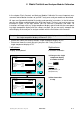
In the chapter "Basic Controls and Analyzer Module Calibration" the most important mea-
surement and calibration functions of your MLT analyzer or analyzer module are described.
All steps are figured with detailed illustrations and operation instructions. In the left column
you can see display and keyboard of the NGA front panel. The keys you have to press are
illustrated in black. In the right column you can read the instructions and notes. All
instructions will begin with any single component display and will end with the correspond-
ing single component display after the setups are done. So you can easily compare the
actual display of the analyzer or analyzer module with the illustrations of the manual.
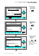
Example: You want to change from the single component display of channel 1(CO
2
) to
the single component display of channel 2 (CO).
• Picture one shows the starting situation: single component display of CO
2
.
• Picture two shows the result you get if you press the F4 key (Channel):
single component display of CO.
Left column: Right column:
Display and keyboard Instructions and notes
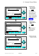
Display Status... Main... Channel Calib...
MLT25/CH1/R2
F1 F2 F3 F4 F5
0.0 100.0Temperature: 25.0 C
Maintenance-Requests: No
Any_Alarms: No
Operation: Ready
Range: 2
2.50 %CO2
0 5.00
Display Status... Main... Channel Calib...
MLT25/CH2/R2
Temperature: 25.0 C
Maintenance-Requests: No
F1 F2 F3 F4 F5
95.00 ppm CO
0 250
Range: 2
0.0 100.0
Any_Alarms: No
Operation: Ready
⇒ ⇒ Change to the single
component display
of another channel
Press
F4
Example:
Changing from
CO2 (Channel 1) to
CO (Channel 2)
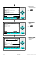
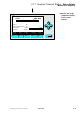
⇒ ⇒ Next instruction
or step