
MLT Analyzer Module Manual


NGA-2000 System Calibration
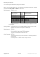
Supplement - 24 NGA 2000 90003482(2) [NGA-e (MLT-Software 3.2.X)] 07/98
4 Functionality
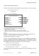
4.1 Gas flow
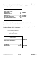
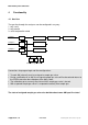
The gas flow through the analyzers can be configured in any way:
1. only serial
2. only parallel
3. serial and parallel mixed
Sample 1 V1 AM1 AM2 AM3
Sample 2 V2 AM4
Sample 3 V3 AM5
V 4 V 5 V 6
Calibration gas mixtures
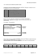
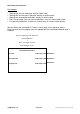
Connections for program logic and flow configurations:
• To each AM (channel) must be assigned a sample gas valve.
• During a calibration of an AM the assigned sample gas valve will be closed and returns to
the OPEN-state after the calibration of the AM is done.
• The calibration gases can only flow into an AM if sample gas valve is closed.
• With a opened sample gas valve it is expected to actually flow sample gas.
The state of assigned sample gas valve also decides about some AM specific states!