Instruction Manual IB-106-300NH Rev. 4.2 July 2002 World Class 3000 Oxygen Analyzer with IFT 3000 Intelligent Field Transmitter http://www.processanalytic.
ESSENTIAL INSTRUCTIONS READ THIS PAGE BEFORE PROCEEDING! Rosemount Analytical designs, manufactures and tests its products to meet many national and international standards. Because these instruments are sophisticated technical products, you MUST properly install, use, and maintain them to ensure they continue to operate within their normal specifications.
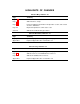
HIGHLIGHTS OF CHANGES Effective May, 1999 Rev. 4.0 Page Summary Page P-6 Added new Quick Start Guide. Page 3-1 Added Section 3, Setup. Page 4-1 Removed calibration information from Operation section, and created Section 4, Calibration. Page 6-2 Expanded explanations of IFT status codes. Section 6 Added new troubleshooting procedures. Effective November, 2001 Rev. 4.1 Page Summary Highlights Updated Highlights of Changes Appendix A page. Appendix A Replaced Appendix A, Rev. 3.6 with Rev. 3.
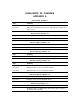
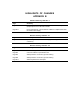
HIGHLIGHTS OF CHANGES APPENDIX A Effective May, 1996 Rev. 3 Page Summary -- General. Updated appendix to reflect probe design changes. Page A-13 Added “Extended temperature by-pass arrangements” to Figure A-13 (Sheet 3 of 3) Effective June, 1996 Rev. 3.1 Page Summary Page A-13 Updated part ordering information. Effective August, 1996 Rev. 3.2 Page Summary Page A-25 Updated cell replacement kit part numbers for the probe. Effective October, 1996 Rev. 3.
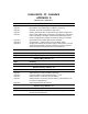
HIGHLIGHTS OF CHANGES (CONTINUED) Effective November, 2001 Rev. 3.7 Page Summary A-8 Added new cup type diffusion assembly description, paragraph A-6.e. and diffusion assembly illustrations, Figure A-13 and A-14. A-26 Added new cup type diffusion assembly part numbers 4851B89G04 and 4851B90G04 to replacement parts list. Deleted stainless steel diffuser assembly from replacement parts list. Effective July, 2002 Rev. 3.8 Page Summary A-13 Added troubleshooting symptoms 5 and 6 to Table A-2.
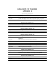
HIGHLIGHTS OF CHANGES APPENDIX B Effective February, 1992 Rev. 2 Page Summary Page B-1 Figure B-1. New HPS 3000 Optional Class 1, Division 1, Group B (IP56) Explosion-Proof Enclosure added. Page B-11 Figure and Index No. column added to Table B-2. Replacement Parts for Heater Power Supply. Effective January, 1995 Rev. 2.1 Page Summary Page B-3 Updated Figure B-3, Heater Power Supply Block Diagram for IB consistency. Effective January, 1997 Rev. 2.
HIGHLIGHTS OF CHANGES APPENDIX D Effective June, 1994 Rev. 2 Page Summary Page D-1 Page D-2 Page D-3 Page D-4 Page D-7 MPS outline drawing changed to show new MPS. MPS interior view replaced with new MPS in Figure D-2. "Optional" for check valve deleted in Figure D-3. Drawing showing location of optional Z-Purge added as Figure D-4. Power supply replacement procedures in paragraph D-7 changed to reflect new design in the MPS.
HIGHLIGHTS OF CHANGES APPENDIX E Effective May, 1996 Rev. 4 Page Summary --- General. Updated text and illustrations to reflect new version of IFT. Page E-4 Updated IFT display status codes and placed in priority sequence. Effective June, 1996 Rev. 4.1 Page Summary Page E-2 Updated specification table. Effective October, 1996 Rev. 4.2 Page Summary Page E-4 Added new status displays for password protection features. Effective January, 1997 Rev. 4.
HIGHLIGHTS OF CHANGES APPENDIX J Effective April, 1995 Rev. 1 Page Summary Page J-13 Added statement of reference to the return authorization number. Effective June, 1995 Rev. 1.1 Page Summary — Figure J-4. Updated figure to include “Status group” and “K3 eff” in calculations.
Instruction Manual IB-106-300NH Rev. 4.2 July 2002 World Class 3000 TABLE OF CONTENTS PREFACE........................................................................................................................ P-1 Definitions ........................................................................................................................ P-1 Safety Instructions .......................................................................................................... P-2 Glossary of Terms ......
Instruction Manual IB-106-300NH Rev. 4.2 July 2002 World Class 3000 7-0 RETURN OF MATERIAL .............................................................................................. 7-1 8-0 APPENDICES ................................................................................................................. 8-1 Appendix A ..................................................................................................................... A-1 Appendix B ........................................
Instruction Manual IB-106-300NH Rev. 4.2 July 2002 World Class 3000 LIST OF TABLES Table 4-1. Table 5-1. Table 5-2. Table 5-3. Table 5-4. Table 5-5. Table 5-6. Table 6-1. Table 6-2. Table 6-3. Table 6-4. Table 6-5. Table 6-6. Rosemount Analytical Inc. Automatic Calibration Parameters ......................................................................... 4-8 Sample HELP Messages....................................................................................... 5-3 MAIN menu ........................
Instruction Manual IB-106-300NH Rev. 4.2 July 2002 iv World Class 3000 Rosemount Analytical Inc.
Instruction Manual IB-106-300NH Rev. 4.2 July 2002 World Class 3000 ! NOTE Only one probe can be calibrated at a time. Probe calibrations must be scheduled appropriately in multiple probe applications. PREFACE The purpose of this manual is to provide a comprehensive understanding of the World Class 3000 Oxygen Analyzer components, functions, installation, and maintenance. This manual is designed to provide information about the World Class 3000 Oxygen Analyzer.
Instruction Manual IB-106-300NH Rev. 4.2 July 2002 World Class 3000 IMPORTANT SAFETY INSTRUCTIONS FOR THE WIRING AND INSTALLATION OF THIS APPARATUS The following safety instructions apply specifically to all EU member states. They should be strictly adhered to in order to assure compliance with the Low Voltage Directive. NonEU states should also comply with the following unless superseded by local or National Standards. 1.
Instruction Manual IB-106-300NH Rev. 4.2 July 2002 World Class 3000 GLOSSARY OF TERMS Abrasive Shield An optional component that shields the probe from high velocity particulate entrained in the flue gas stream. Automatic Calibration An automatic calibration can only be performed if the system is equipped with an MPS 3000 Multiprobe Calibration Gas Sequencer. Once a calibration is initiated by the operator or by the IFT on a scheduled interval, all calibration actions are performed by the IFT.
Instruction Manual IB-106-300NH Rev. 4.2 July 2002 World Class 3000 Reference Air Provides a known oxygen concentration to the reference side of the oxygen sensing cell. Semiautomatic Calibration Semiautomatic calibration is performed when the system does not include an MPS 3000 Multiprobe Calibration Gas Sequencer. The IFT 3000 provides prompts to direct the user to switch calibration gases when performing the calibration. Thermocouple An electrical device made of two dissimilar metals.
Instruction Manual IB-106-300NH Rev. 4.2 July 2002 World Class 3000 WHAT YOU NEED TO KNOW BEFORE INSTALLING AND WIRING A ROSEMOUNT IFT 3000 INTELLIGENT FIELD TRANSMITTER WITH WORLD CLASS 3000 PROBE 1. What is the line voltage being supplied to the IFT 3000? Write the line voltage here __________ 2. Use the following drawing, Figure 1, to identify which parts of the World Class 3000 system are included in your system. Components in the shaded area are optional components.
Instruction Manual IB-106-300NH Rev. 4.2 July 2002 World Class 3000 QUICK START GUIDE Use this Quick Start Guide if ... 1. You are using a World Class 3000 probe. 2. You are NOT using any optional components. Optional components are shown in the shaded area in Figure 1. 3. You are familiar with the installation requirements for the IFT 3000 Intelligent Field Transmitter and World Class 3000 probe. 4.
Instruction Manual World Class 3000 IB-106-300NH Rev. 4.2 July 2002 QUICK START GUIDE FOR IFT 3000 SYSTEMS Before using the Quick Start Guide, please read “WHAT YOU NEED TO KNOW BEFORE INSTALLING AND WIRING A ROSEMOUNT IFT 3000 INTELLIGENT FIELD TRANSMITTER WITH WORLD CLASS 3000 PROBE” on the preceding page. 1. Install the probe in an appropriate location on the stack or duct. Refer to Section 2, paragraph 2-1a for information on selecting a location for the probe. 2.
Instruction Manual IB-106-300NH Rev. 4.
Instruction Manual World Class 3000 IB-106-300NH Rev. 4.2 July 2002 QUICK REFERENCE GUIDE IFT 3000 INTELLIGENT FIELD TRANSMITTER Performing a Manual (Semiautomatic) Calibration 1. Connect the high calibration gas to the probe fitting. 2. Press the CAL key. 3. Select the PERFORM CALIBRATION sub-menu. 4. Press the ENTER key. 5. Turn on the high calibration gas. 6. When the O2 reading is stable, press ENTER. 7. Turn off the high calibration gas and turn on the low calibration gas. 8. Press Enter. 9.
Instruction Manual IB-106-300NH Rev. 4.2 July 2002 World Class 3000 HART COMMUNICATOR FAST KEY SEQUENCES Perform Calibration 2 3 1 Analog Output Upper Range Value 3 3 Trim Analog Output 2 4 3 1 4 Analog Output Lower Range Value 3 Toggle Analog Output Tracking 2 2 2 5 View O2 Value 2 1 1 1 View Analog Output 1 2 1 Technical Support Hotline: For assistance with technical problems, please call the Customer Support Center (CSC). The CSC is staffed 24 hours a day, 7 days a week.
Instruction Manual IB-106-300NH Rev. 4.2 July 2002 World Class 3000 1 SECTION 1 DESCRIPTION AND SPECIFICATIONS 1-1 COMPONENT CHECKLIST OF TYPICAL SYSTEM (PACKAGE CONTENTS) mitter should contain the items shown in Figure 1-1. Record the part number, serial number, and order number for each component of your system in the table located on the first page of this manual. A typical Rosemount World Class 3000 Oxygen Analyzer with IFT 3000 Intelligent Field Trans- 1. 2. 3. 4. 5. 6. 7.
Instruction Manual IB-106-300NH Rev. 4.2 July 2002 1-2 SYSTEM OVERVIEW a. Scope This Instruction Bulletin has been designed to supply details needed to install, startup, operate, and maintain the Rosemount World Class 3000 Oxygen Analyzer with IFT 3000 Intelligent Field Transmitter. The Intelligent Field Transmitter (IFT) can be interfaced with one World Class 3000 probe. The IFT provides all necessary intelligence for controlling the probe and optional MPS 3000 Multiprobe Calibration Gas Sequencer.
Instruction Manual IB-106-300NH Rev. 4.2 July 2002 World Class 3000 c. System Configuration The equipment covered in this manual consists of three major components: the oxygen analyzer (probe), the intelligent field transmitter (IFT), and an optional heater power supply (HPS). The HPS is required where the cable run between the probe and the electronics is greater than 150 ft (45 m). There is also an optional multiprobe calibration gas sequencer (MPS) to facilitate automatic calibration of the probe.
Instruction Manual IB-106-300NH Rev. 4.2 July 2002 World Class 3000 9. An operator can set up, calibrate, or troubleshoot the IFT in one of two ways: (a) Optional General User Interface (GUI). The GUI is housed within the IFT electronics enclosure and makes use of an LCD and keypad. (b) Optional HART Interface. The IFT's 4-20 mA output line transmits an analog signal proportional to oxygen level. The line also carries all information normally accessed by use of the General User Interface LCD and keypad.
Instruction Manual IB-106-300NH Rev. 4.2 July 2002 World Class 3000 GASES STANDARD DUCT STACK CALIBRATION GAS ADAPTER PLATE OXYGEN ANALYZER (PROBE) INSTRUMENT AIR SUPPLY (REF. AIR) } PRESSURE REGULATOR LINE VOLTAGE FLOWMETER GASES OPTIONS DUCT INTELLIGENT FIELD TRANSMITTER STACK ADAPTER PLATE MULTIPROBE CALIBRATION GAS SEQUENCER CAL GAS 1 CAL GAS 2 INST.
Instruction Manual IB-106-300NH Rev. 4.2 July 2002 World Class 3000 2-Conductor T/C Wire [150 Ft (45 m) Max] (optional) (OPTIONAL) Line Voltage 4 Twisted Pair Plus 2 Twisted Pair for Options [1200 Ft (364 m) Max] Line Voltage Stack Thermocouple (optional) 7-Conductor Cable [150 Ft (45 m) Max] HPS 3000 HPS 3000 Explosion Proof Required only for Hazardous Area Applications, otherwise use NEMA 4X. Lengths Exceeding 150 ft (45 m).
Instruction Manual World Class 3000 IB-106-300NH Rev. 4.2 July 2002 After selecting the probe mounting location, provision should be made for a platform where the probe can be easily serviced. The intelligent field transmitter (IFT) can be located up to 150 ft (45 m) cabling distance from the probe when used without optional heater power supply (HPS).
Instruction Manual IB-106-300NH Rev. 4.2 July 2002 1-8 Description and Specifications World Class 3000 Rosemount Analytical Inc.
Instruction Manual IB-106-300NH Rev. 4.2 July 2002 World Class 3000 SECTION 2 INSTALLATION 2 2-1 OXYGEN ANALYZER (PROBE) INSTALLATION Before starting to install this equipment, read the "Safety instructions for wiring and installation of this apparatus" at the front of this Instruction Bulletin. Failure to follow the safety instructions could result in serious injury or death. a. Selecting Location 1.
Installation Rosemount Analytical Inc. 5.71 (145) 0.71 (18) 7.28 (185) DIN 4512C19H01 81.3 (2065) 117.3 (2980) 34 (864) 70 (1778) 106 (2692) 142 (3607) 3 FT 6 FT 9 FT 12 FT DIM "B" 16 (406) 18 IN. 153.3 (3894) 45.3 (1151) 27.3 (694) DIM "A" PROBE 5.12 (130) 0.59 (15) 6.10 (155) REF AIR ANSI 1/4 IN. TUBE DIN 6 MM TUBE 6 MM TUBE JIS CAL GAS 27270009 2. THESE FLAT FACED FLANGES ARE MANUFACTURED TO ANSI, DIN, AND JIS BOLT PATTERNS AND ARE NOT PRESSURE RATED. NOTES: 1.
Rosemount Analytical Inc. 103.1 (2619) 139.1 (3533) 81.3 (2065) 117.3 (2980) 153.3 (3894) 63 (1600) 99 (2515) 135 (3429) 6 FT 9 FT 12 FT A Division of Emerson Process Management 3.6 NOMINAL 0.945 0.75 0.75 (8) HOLES DIAMETER 7.48 7.48 7.50 BOLT CIRCLE INSULATE IF EXPOSED TO AMBIENT WEATHER CONDITIONS SEE TABLE IV FOR FLANGE SIZES 7.00 (178) CHECK VALVE FOR CAL GAS LINES ELECTRICAL CONNECTOR DIM "D" REMOVAL ENVELOPE 14.5 (369) 5.
2-4 Installation 0.625-11 4.75 (121) "B" THREAD "C" DIA 5.708 (145) (M-16 x 2) 7.5 (191) DIN (P/N 4512C36G01) B C 45o A 7.50 (191) "D" DIA Rosemount Analytical Inc. 4 STUDS, LOCKWASHERS AND NUTS EQUALLY SPACED ON C DIA B.C. ADAPTOR PLATE FOR 3, 6, 9, AND 12 FT ABRASIVE SHIELD INSTALLATIONS. SEE SHEET 2. A B CROSSHATCHED AREA IN 4 CORNERS MAY BE USED TO PROVIDE ADDITIONAL HOLES FOR FIELD BOLTING OF PLATE TO OUTSIDE WALL SURFACE. A C 22.5o 16860021 ABRASIVE SHIELD FLANGE O.D.
Instruction Manual IB-106-300NH Rev. 4.2 July 2002 World Class 3000 INSTALLATION FOR METAL WALL STACK OR DUCT CONSTRUCTION INSTALLATION FOR MASONRY WALL STACK CONSTRUCTION 2 0.50 [13] 0.50 [13] BOLT ADAPTOR PLATE TO OUTSIDE WALL SURFACE FIELD WELD PIPE TO ADAPTOR PLATE 3.
Instruction Manual IB-106-300NH Rev. 4.2 July 2002 World Class 3000 NOTE: DIMENSIONS IN INCHES WITH MILLIMETERS IN PARETHESES. BRACE BARS (NOT BY ROSEMOUNT) 2.00 (51) } VERTICAL BRACE CLAMP ASSY. BY ROSEMOUNT HORIZONTAL BRACE CLAMP ASSY. (BOTH BRACE CLAMP ASSEMBLIES ARE THE SAME. INSTALLATION AND LOCATION OF CLAMP ASSEMBLIES AND BRACE BARS TO BE DONE IN FIELD.) o 60 MAX. 1.00 (25) 30o MIN. 2 HOLES - 0.625 (16) DIA. FOR 0.50 (12) DIA. BOLT 5.62 (143) ABRASIVE SHIELD 4.12 (105) 4.12 (105) 0.
Instruction Manual IB-106-300NH Rev. 4.2 July 2002 World Class 3000 4. If using the optional ceramic diffusor element, the vee deflector must be correctly oriented. Before inserting the probe, check the direction of flow of the gas in the duct. Orient the vee deflector on the probe so that the apex points upstream toward the flow (Figure 2-2). This may be done by loosening the setscrews, and rotating the vee deflector to the desired position. Retighten the setscrews. 5.
Instruction Manual IB-106-300NH Rev. 4.2 July 2002 World Class 3000 c. Reference Air Package maximum at 2 scfh (56.6 L/hr) maximum; supplied by one of the following (less than 40 parts-per-million total hydrocarbons). Regulator outlet pressure should be set at 5 psi (35 kPa). After the oxygen analyzing (probe) unit is installed, connect the reference air set to the probe junction box. The reference air set should be installed in accordance with Figure 2-3. (a) Instrument air - clean, dry. d.
Instruction Manual IB-106-300NH Rev. 4.2 July 2002 World Class 3000 2-2 INTELLIGENT FIELD TRANSMITTER (IFT) INSTALLATION 11.24 (285.5) 0.31 (7.9) 8.00 (203.2) a. Mechanical Installation 2 The outline drawing of the IFT module in Figure 2-4 shows mounting centers and clearances. The NEMA 4X enclosure is designed to be mounted on a wall or bulkhead. The IFT should be installed no more than 1200 feet (364 m) from the optional HPS or 150 feet (45 m) from the probe if HPS is not installed in the system.
Instruction Manual IB-106-300NH Rev. 4.2 July 2002 World Class 3000 if MPS is installed in the system. Refer to Figure 2-8, note 6. Do not install jumper JM6 on the microprocessor board, or JM1 on the interconnect board, if an HPS is installed in the system. This will result in system failure. 5. The power cable should comply with the safety regulations in the user's country and should not be smaller than 16 gauge, 3 amp. 6.
Instruction Manual IB-106-300NH Rev. 4.2 July 2002 World Class 3000 NOTE General Wiring Recommendations To maintain CE compliance and ensure proper EMC performance, all signal wires to the Interconnect Board, with the exception of the probe cable, should be looped through the ferrite beads provided as shown in Figure 2-6 (P/N 1L04253H01). Signal wires may be grouped together and looped through before exiting the enclosure. Ferrite beads should be placed as close as possible to the exit point.
Instruction Manual IB-106-300NH Rev. 4.2 July 2002 World Class 3000 FUSES FUSES NOTE: ALL FUSES (F1 THROUGH F5) ARE 5A @ 250 VAC, ANTISURGE, CASE SIZE 5 X 20 MM, TYPE T TO IEC127, SCHURTER. Figure 2-7. IFT Power Supply Board Jumpers 2-12 Installation Rosemount Analytical Inc.
Instruction Manual IB-106-300NH Rev. 4.2 July 2002 World Class 3000 GN WH BK H RD PROBE TC - E YE PROBE TC + R BL OR PROBE MV - 2 V 3D39122G REV POWER SUPPLY BOARD J1 1 2 3 4 5 6 7 8 PROBE MV + JM7 I } HEATER 3D39513G MICROPROCESSOR BOARD BK GN BK YE CHROMEL RD ALUMEL GN CELL -VE OR CELL +VE PROBE JUNCTION BOX WIRING CURRENT/VOLTAGE SELECTOR SWITCH ALWAYS DISCONNECT LINE VOLTAGE FROM INTELLIGENT FIELD TRANSMITTER BEFORE CHANGING JUMPERS.
Instruction Manual IB-106-300NH Rev. 4.2 July 2002 World Class 3000 OUTPUT JUMPER HPS Remove JM6 Probe (No HPS) Install JM6 ANALOG OUTPUT (Condition during microcontroller failure) Jumper Output = zero Install JM7 Output = maximum Remove JM7 chart recorders. Relay outputs are typically sent to annunciators. 3. Relays K1 and K2 are user configurable from the probe SETUP sub-menu (Table 5-5). Typically these are used to indicate O2 values above or below specified tolerances.
Instruction Manual IB-106-300NH Rev. 4.2 July 2002 World Class 3000 CURRENT/VOLTAGE SELECTOR SWITCH TO I/O BOARD JM7 JM7 J4 2 SW1 JM6 +30VISO-C GNDC +5VISO-C TP7 TP1 -5V J3 TO POWER SUPPLY CARD J1 J2 TP2 +15V TP8 +5V TP3 -15V TP4 TP5 TP6 JM6 TO GUI CARD TO LDP CARD 3D39513G REV 29850004 Figure 2-10. IFT Microprocessor Board Rosemount Analytical Inc.
Instruction Manual IB-106-300NH Rev. 4.2 July 2002 World Class 3000 OUTPUT JUMPER HPS Remove JM1 Probe (No HPS) Install JM1 Figure 2-11. Interconnect Board Jumper Configuration NOTES: DENOTES SHIELD CONNECTION. OK RELAY IS ENERGIZED WHEN UNIT IS FUNCTIONING PROPERLY.
Instruction Manual IB-106-300NH Rev. 4.2 July 2002 World Class 3000 NOTE: DIMENSIONS IN INCHES WITH MILLIMETERS IN PARENTHESES. 3.25 (82.6) 7.00 (177.8) 3.63 (92.2) 10.39 (264) 2 NEMA 4X (NON-HAZARDOUS) 0.13" (3.3) THK U. L. APPROVED GASKET 0.31 (7.9) 6.00 (152.4) 4.00 (101.6) 8.50 (215.9) 1.81 (46) 4.88 (124) 6.75 (171.5) 8.50 (215.9) 9.96 (253) 4.38 (111.3) 0.38 (9.7) 11.00 (279.4) 8.00 (203.2) 9.17 (233) 1.00 (25.4) MINIMUM CLEARANCE FOR REMOVING COVER 6.18 (156.9) 4.72 (120) #0.
Instruction Manual IB-106-300NH Rev. 4.2 July 2002 World Class 3000 RELAY WIRE IS OPTIONAL, RELAY CAN BE BYPASSED WITH JUMPER JM-2 IF NOT WIRED TO THE IFT. 2 STACK TC WIRING AS REQUIRED. HEATER 3 ALL WIRES #16-#22 AWG TWISTED PAIR WITH SHIELD BY CUSTOMER EXCEPT AS NOTED. } NOTES 1 4 STANDARD PROBE CABLE BETWEEN PROBE AND HPS BY ROSEMOUNT. 5 REMOVE JM1 ON INTERCONNECT BOARD. REMOVE JM6 ON MICROPROCESSOR BOARD. IF RELAY WIRE OF NOTE 1 INSTALLED THEN REMOVE JM2 ON HPS 3000.
Instruction Manual IB-106-300NH Rev. 4.2 July 2002 World Class 3000 CURRENT/VOLTAGE SELECTOR SWITCH 3D39513G MICROPROCESSOR 2 JM7 I BOARD V 3D39122G REV POWER SUPPLY BOARD J1 JM6 ALWAYS DISCONNECT LINE VOLTAGE FROM INTELLIGENT FIELD TRANSMITTER BEFORE CHANGING JUMPERS.
Instruction Manual IB-106-300NH Rev. 4.2 July 2002 World Class 3000 TRANSFORMER SCREW (2 PER COVER) TERMINAL COVERS FRONT TERMINAL STRIP (FROM ELECTRONICS) TRANSFORMER TERMINAL STRIP (FROM ELECTRONICS) SIDE 29850005 Figure 2-15. Heater Power Supply Wiring Connections 2-20 Installation Rosemount Analytical Inc.
Instruction Manual IB-106-300NH Rev. 4.2 July 2002 World Class 3000 2 1 2 NOTES: 1 100 V.A.C. OPERATION REQUIRES TRANSFORMER PART NUMBER 1M02961G02. 2 REFER TO TABLE 3-5 FOR PROPER SET POINT SELECTION. 0310122 Figure 2-16. Jumper Selection Label NOTE Before supplying power to the heater power supply, verify that jumpers JM3, JM6 are removed and JM7 is installed. If relay wire (Figure 2-14, note 1) is installed, JM2 must be removed from HPS Mother Board (Figure 2-17). 4.
Instruction Manual IB-106-300NH Rev. 4.2 July 2002 2-4 World Class 3000 MULTIPROBE CALIBRATION GAS SEQUENCER INSTALLATION b. Gas Connections a. Mechanical Installation The outline drawing of the MPS module in Figure 2-18 shows mounting centers and clearances. The box is designed to be mounted on a wall or bulkhead. The MPS module should be installed no further than 300 feet (91 mz) piping distance from the probe, and no more than 1000 feet (303 m) cabling distance from the IFT.
Instruction Manual IB-106-300NH Rev. 4.2 July 2002 World Class 3000 3. Connect the low O2 calibration gas to LOW GAS. The calibration gas pressure should be set at 20 psi (138 kPa). more than one probe system is being used, the additional probes and electric packages would be wired similar to the first probe. 4. Connect the REF AIR OUT to the reference air fitting on the probe junction box. 2 NOTE Refer to Figure 2-20 for fuse locations and specifications. 5.
Instruction Manual IB-106-300NH Rev. 4.2 July 2002 World Class 3000 NOTE: FUSES FOR 115 VOLT MPS UNIT ARE FAST ACTING, 1A @ 250 VAC, SIZE: 1/4 IN. DIA X 1-1/4 IN. LG., GLASS BODY, NON-TIME DELAY, BUSSMAN PART NO. BK/AGC-1 (ROSEMOUNT APRT NO. 138799-004). MH1 J1 MH2 J2 IFT INTERCONNECT BOARD J3 FUSES FOR 220 VOLT MPS UNIT ARE FAST ACTING, 0.5 A @ 250 VAC, SIZE 1/4 IN. DIA. X 1-1/4 IN. LG., GLASS BODY, NON-TIME DELAY, BUSSMAN PART NO. BK/AGC-1/2 (ROSEMOUNT PART NO. 138799-014).
Instruction Manual IB-106-300NH Rev. 4.2 July 2002 World Class 3000 NOTE Upon completing installation, make sure that the probe is turned on and operating prior to firing up the combustion process. Damage can result from having a cold probe exposed to the process gases. 2 Power down all probes during outages. Sensor chamber is heated to 736°C. Further, if ducts will be washed down during the outage, remove the probes to prevent water damage. Rosemount Analytical Inc.
Instruction Manual IB-106-300NH Rev. 4.2 July 2002 2-26 Installation World Class 3000 Rosemount Analytical Inc.
Instruction Manual IB-106-300NH Rev. 4.2 July 2002 World Class 3000 SECTION 3 SETUP 3-1 OVERVIEW 3. Source Set to Dual Rng O2. Range setup allows you to set the transfer function (Xfer Fnct) to either linear or log output. You can also specify the O2 values represented by the high and low analog output values for both the normal and high range. This section provides information on configuring the IFT 3000 Intelligent Field Transmitter.
Instruction Manual IB-106-300NH Rev. 4.2 July 2002 World Class 3000 alarms, respectively. The Alarm DB parameter allows the setting of an alarm dead band. When a dead band is set, the O2 value must change by the dead band value before the alarm will reset. For example, if the Hi Alarm is set to 8.00% and the dead band is set to 0.25%, the O2 concentration must drop to below 7.75% before the O2 alarm will clear.
Instruction Manual IB-106-300NH Rev. 4.2 July 2002 World Class 3000 SECTION 4 CALIBRATION 4-1 ANALOG OUTPUT CALIBRATION For the analog output to perform within the published specifications, it must be manually calibrated. The only equipment needed to perform the calibration is a voltage or current meter, depending on which mode of operation is to be calibrated. Prior to manual calibration, remove the IFT from any control loops it may be in.
Instruction Manual IB-106-300NH Rev. 4.2 July 2002 2. Calibration Methods There are three calibration methods: manual (semiautomatic), manually initiated automatic, and fully automatic. Manual (semiautomatic) calibration is done without an MPS unit. Calibration gases are switched on and off by the operator and the IFT is sequenced through the calibration procedure by the operator with the front panel keyboard. The IFT prompts the operator for the correct action.
Instruction Manual IB-106-300NH Rev. 4.2 July 2002 World Class 3000 255 Brimley Road Scarborough, Ontario, Canada 416/266-3161 SCOTT ENVIRONMENTAL TECHNOLOGY, INC. SCOTT SPECIALTY GASES maximum and a supply of clean, dry instrument air. 5 Two zero-leakage shutoff valves. 6 Miscellaneous oil-free tubing and fittings. (b) Calibration 2600 Cajon Blvd.
Instruction Manual IB-106-300NH Rev. 4.2 July 2002 World Class 3000 PROBE (END VIEW) CALIBRATE IN-PLACE FITTING CHECK VALVE REFERENCE AIR CONNECTION 2 SCFH 5 SCFH REFERENCE AIR SET FLOW METER INSTR. AIR IN LEAK TIGHT VALVES REG 0.4% O2 8.0% O2 NOTE: PROBE CALIBRATION GAS FITTING HAS A SEAL CAP WHICH MUST BE IN PLACE AT ALL TIMES EXCEPT DURING CALIBRATION. Figure 4-1.
Instruction Manual IB-106-300NH Rev. 4.2 July 2002 World Class 3000 Rosemount France 165 Boulevard de Vallmy 92706, Colombes, France Rosemount P/N 3530B07G01 for probe 0.4% oxygen in nitrogen in disposable bottle. Rosemount P/N 3530B07G02 for probe 8% oxygen in nitrogen in disposable bottle. 3 CALIBRATION GAS KIT #1 (P/N 6296A27G01) A check valve is required at the probe (between the calibration fitting and the gas line) to prevent the migration of process gases down the calibration gas line.
Instruction Manual IB-106-300NH Rev. 4.2 July 2002 CALIBRATE IN PLACE CONNECTION World Class 3000 REFERENCE AIR CONNECTION CALIBRATION GAS HOSE CONNECTS TO CHECK VALVE CHECK VALVE PUSHBUTTON REGULATOR WITH CONTENTS GAGE - SET 5 SCFH 0.4 % O2 NOTE: PROBE CALIBRATION GAS FITTING HAS A SEAL CAP WHICH MUST BE IN PLACE EXCEPT DURING CALIBRATION. 8.0 % O2 27270005 Figure 4-3. Typical Portable Calibration Setup d.
Instruction Manual IB-106-300NH Rev. 4.2 July 2002 World Class 3000 PROBE (END VIEW) OPTIONAL CHECK VALVE CALIBRATION GAS IFT HPS REFERENCE AIR PROBE SIGNAL CONNECTIONS 4 MPS-IFT SIGNAL CONNECTIONS MPS INSTRUMENT AIR IN NOTE: THE MPS CAN BE USED WITH UP TO FOUR PROBES. ONLY ONE PROBE CAN BE CALIBRATED AT A TIME. PROBE CALIBRATIONS MUST BE SCHEDULED IN MULTIPLE PROBE APPLICATIONS. NOTE: SHOWN WITH HPS OPTION. CALIBRATION CALIBRATION GAS 2 GAS 1 (LOW O2) (HIGH O2) 27270006 Figure 4-4.
Instruction Manual IB-106-300NH Rev. 4.2 July 2002 World Class 3000 Table 4-1. Automatic Calibration Parameters Auto Cal YES/NO Set to YES Output Tracks YES/NO Set as desired to configure analog output tracking. 4-8 2. Fully Automatic Calibration Setup. In order for the IFT system to calibrate automatically, the parameters from the CALIBRATE sub-menu (shown in Table 4-1) in the IFT have to be entered. Cal Intvl XD XH Set the desired time between calibrations in number of days and hours (1 year max).
Instruction Manual IB-106-300NH Rev. 4.2 July 2002 World Class 3000 Calibration Record For Rosemount Analytical In Situ O2 Probe Probe Serial Number: Probe Tag Number: Probe Location: Date Placed Into Service: Date Slope Constant Impedance Responseinitial Responsefinal 4 Notes: Responseinitial Responsefinal Rosemount Analytical Inc. When the second calibration gas is turned off, note the number of seconds required for the O2 value to begin migrating back to the process value.
Instruction Manual IB-106-300NH Rev. 4.2 July 2002 4-10 Calibration World Class 3000 Rosemount Analytical Inc.
Instruction Manual World Class 3000 IB-106-300NH Rev. 4.2 July 2002 SECTION 5 GENERAL USER INTERFACE (GUI) OPERATION 5-1 OVERVIEW b. HART Communicator Interface Devices Ensure that the oxygen analyzer, heater power supply, and intelligent field transmitter have been properly connected. It is important to check that grounding and screening of terminations are correctly made to prevent the introduction of ground loops.
Instruction Manual IB-106-300NH Rev. 4.2 July 2002 5-2 World Class 3000 DELUXE VERSION IFT DISPLAYS AND CONTROLS 3 10 1 11 4 2 CA TG L TGH L 5 HE LP 12 DAT A ES C CA L SE TU P EN TE R 13 6 7 NOTE: IFT COVER DOOR SHOWN FOR REFERENCE. 8 9 INTERNAL VIEW EXTERNAL VIEW 21190003 Figure 5-1. Deluxe Version IFT Displays and Controls 5-2 Figure 5-1 Index No. Control/LED 1 LCD Display Top line displays system status, menu, and probe number.
Instruction Manual IB-106-300NH Rev. 4.2 July 2002 World Class 3000 Table 5-1. Sample HELP Messages MENU, SUB-MENU, HELP OR PARAMETER NAME MESSAGE PROBE DATA Press ENTER key to access DATA menu. CALIBRATE O2 The CAL menu is used to start calibration and view calibration. SETUP The SETUP menu is used to configure the IFT 3000. 5-3 5-5 HELP KEY The quick reference chart (Figure 5-2) is designed to help you get where you want to be in the menu system.
Instruction Manual IB-106-300NH Rev. 4.2 July 2002 5-8 World Class 3000 CALIBRATE O2 SUB-MENU 5-9 The CALIBRATE O2 sub-menu (Table 5-4) is used to enter the calibration mode. To access the CALIBRATE O2 sub-menu, press the CAL key at any time. The increase and decrease keys are used to scroll through the list. SETUP SUB-MENU The SETUP sub-menu is used to enter all operator set variables into the system. To access the SETUP sub-menu press the SETUP key at any time.
Instruction Manual IB-106-300NH Rev. 4.2 July 2002 World Class 3000 O2 PROCESS DATA Efficiency Stack Temp Cell TEMPERATURE Stack Cold Junct Cell PROBE DATA DIAGNOSTIC DATA Cell T/C VOLTAGES Stk T/C Cold Jnt 5 Analog OUTPUT VALUES K1 State K2 State Slope PERFORM CALIBRATION LATEST CALIBRATION Constant Resist Slope CALIBRATE O2 VIEW CONSTANTS PREVIOUS CAL Constant Resist Next Cal CALIBRATION STATUS (CONTINUED ON SHEET 2) Slope Constant Resist 686022 Figure 5-2.
Instruction Manual IB-106-300NH Rev. 4.2 July 2002 World Class 3000 CALIBRATION See sheet 4 (CONTINUED FROM SHEET 1) SLOPE 34.5 mV/D57.5 mV/D CONSTANT -20.0 mV20.0 mV SET POINT 736oC 843oC O2 CALIBRATION SETUP RESET SLOPE AND CONST HI ALARM O2 ALARMS LO ALARM ALARM DB EFFICIENCY CALC 0.1000% O225.00% O2 0.00% O225.00% O2 ENABLE CALC Yes No K1 VALUE K2 VALUE 0.00001.000 K3 VALUE 0.000020.
Instruction Manual IB-106-300NH Rev. 4.2 July 2002 World Class 3000 (CONTINUED FROM SHEET 2) O2 Efficiency SOURCE Dual Rng O2 HART 4-20 mA ANALOG OUTPUTS AOUT TYPE 0-20 mA 0-10 V (CONTINUED FROM SHEET 2) See sheet 5 RANGE SETUP 5 SETUP USA GBR COUNTRY FRA ESP GER 27270004 Figure 5-2. Quick Reference Chart (Sheet 3 of 5) Rosemount Analytical Inc.
Instruction Manual IB-106-300NH Rev. 4.2 July 2002 World Class 3000 HIGH GAS 0.1000% O2 25.00% O2 LOW GAS 0.1000% O2 25.00% O2 AUTO CAL Yes No OUTPUT TRACKS Yes No Off, CALIBRATION CAL INTRVL (1 hour to 365 days and no hours) 1H 365 D OH (CONTINUED FROM SHEET 2) Disabled, NEXT CAL (1 hour to 365 days and no hours) 1H 365 D OH GAS TIME 00:30 20:00 PURGE TIME 00:30 20:00 RES ALARM 50 Ω 10000 Ω 16860025 Figure 5-2.
Instruction Manual IB-106-300NH Rev. 4.2 July 2002 World Class 3000 Range Setup (Source not set to: Dual Rng O2) (CONTINUED FROM SHEET 3) XFER FNCT Log LIN RANGE VALUES HIGH END 0.000% O2 25.00% O2 LOW END 0.000% O2 25.00% O2 RANGE SETUP XFER FNCT Log LIN 5 Range Setup (Source not set to: Dual Rng O2) NORMAL RANGE VALUES HIGH END 0.000% O2 25.00% O2 LOW END 0.000% O2 25.00% O2 RANGE MODE Normal Auto High HIGH IN CAL Yes No SWITCHES AT 0.000% O2 25.00% O2 LOW END 0.000% O2 25.
Instruction Manual IB-106-300NH Rev. 4.2 July 2002 World Class 3000 Table 5-4. CALIBRATE O2 Sub-Menu SUB-MENU SELECTION Perform Calibration SETUP SETTING (SEE TABLE 3-5) Auto Cal in Probe Setup is YES Auto Cal in Probe Setup is NO. DISPLAY DESCRIPTION Press ENTER to start Auto Calibration. Starting Automatic Calibration MPS will start calibrating probe. High Gas _____% O2 Time Left 0:00 Value for high O2 calibration gas. Amount of time necessary to complete the current testing phase in min:sec.
Instruction Manual IB-106-300NH Rev. 4.2 July 2002 World Class 3000 Table 5-4. CALIBRATE O2 Sub-Menu (continued) SUB-MENU SELECTION View Constants Calibration Status SETUP SETTING (SEE TABLE 3-5) DISPLAY DESCRIPTION Latest Calibration Slope _____mV/D Constant _____mV Resist _____ohms Slope for probe from latest calibration. Latest calibration offset for probe. Latest calibration resistance of probe.
Instruction Manual IB-106-300NH Rev. 4.2 July 2002 World Class 3000 Table 5-5. SETUP Sub-Menu SUB-MENU SELECTION Calibration O2 Calculation PARAMETERS High Gas ____% O2 Low Gas ____% O2 Auto Cal Output Tracks Cal Intrvl YES/NO YES/NO XD XH Next Cal XH Gas Time 0:30 - 20:00 Purge Time 0:30 - 20:00 Res Alarm Slope Constant Set Point 50 W – 10 kW ____ mV/D ____ mV ____°C DESCRIPTION Value of high O2 calibration gas (0.1000% - 25.00% O2). Value of low O2 calibration gas (0.1000% - 25.00% O2).
Instruction Manual IB-106-300NH Rev. 4.2 July 2002 World Class 3000 Table 5-5. SETUP Sub-Menu (continued) SUB-MENU SELECTION Relay Outputs PARAMETERS DESCRIPTION NOTE K1 and K2 relay outputs can be configured for "OFF" or any one of the eight events listed below. Up to three events can control each relay output. Events are selected in the SETUP sub-menu. K1 Setup K2 Setup Analog Output Event 1 Event 2 Event 3 Event 1 Event 2 Event 3 SOURCE 1. 2. 3. 4. 5. 6. 7. 8.
Instruction Manual IB-106-300NH Rev. 4.2 July 2002 World Class 3000 Table 5-5. SETUP Sub-Menu (continued) SUB-MENU SELECTION Analog Output (continued) PARAMETERS RANGE SETUP (Source set to Dual Rng O2) Xfer Fnct DESCRIPTION Log Lin Select the transfer function used on the analog output. Selecting Log will not effect the output when Efficiency is selected as the Source. Normal Range Values Enter the upper and lower analog output range values for Normal Operating Range.
Instruction Manual IB-106-300NH Rev. 4.2 July 2002 World Class 3000 SECTION 6 TROUBLESHOOTING 6-1 OVERVIEW sion circuits are employed on all field terminations and main inputs. When fault finding, the electrical noise being generated in the immediate circuitry of a faulty system should be evaluated. All cable shields must be connected to earth. The system troubleshooting describes how to identify and isolate faults which may develop in the Oxygen Analyzer System.
Instruction Manual IB-106-300NH Rev. 4.2 July 2002 World Class 3000 Table 6-1. IFT Status Codes Off Heater power has been turned OFF by the electronics. The display shows 0% O2. Several conditions may cause the OFF status: 1. The cell heater temperature is below -50°C. The thermocouple wires may be reversed. 2. The cell temperature is more than 70°C above the set point. The heater is out of control. The triac module may have failed. 3. The cell heater thermocouple voltage has remained within +1.
Instruction Manual IB-106-300NH Rev. 4.2 July 2002 World Class 3000 6-4 HEATER PROBLEM b. The displayed O2 value will read 0%. For all heater troubleshooting, allow at least 30 minutes for the operating temperature to stabilize. After the warmup period, observe the system status and the voltages of the cell TC and the cold junction AD590. For heater related problems: c. Cell TC voltages will vary from normal. These voltages are found by accessing the proper menu.
Instruction Manual IB-106-300NH Rev. 4.2 July 2002 World Class 3000 Table 6-2. Heater Troubleshooting (continued) Problem Cause Corrective Action Status is HtrEr or OFF. Cell TC > 28.4 mV. Cold Junction 273 to 330 mV (normal). O2 Display = 0% 1. Triac failure. Check the triac. Repair as needed. 2. Wrong TC set point. Check electronics manual and verify the set point; typically 1356°F (736°C). 3. Wrong heater voltage selected. HPS voltage jumpers setup wrong.
Instruction Manual IB-106-300NH Rev. 4.2 July 2002 World Class 3000 6-5 CELL PROBLEM For cell troubleshooting, as in heater problems, you should allow at least 30 minutes for operating temperature to stabilize. After this warmup period, observe the system status and cell voltage. If the heater is working, troubleshoot the cell. If the heater is not working, refer to Heater Problem, paragraph 6-4. • The status line may read: Low O2, Hi O2, CalEr, ResHi. • Access voltage values in the proper menu.
Instruction Manual IB-106-300NH Rev. 4.2 July 2002 World Class 3000 Table 6-3. Cell Troubleshooting (continued) Problem Cause Corrective Action Status is ResHi or CalEr. Cell mV = -20 to 120 mV (normal) (continued). 1. Reference air contamination (oil/water). Clean or replace lines and valves as needed. 2. Cell leads reversed. Check cell signal wiring from probe junction box to electronics, and correct wiring if needed. 3. Reference/test gas lines reversed. Switch piping as needed. 4.
Instruction Manual IB-106-300NH Rev. 4.2 July 2002 World Class 3000 6-6 IFT PROBLEM Refer to Table 6-4 to troubleshoot IFT related problems. When an IFT problem is suspected, look at the LED on the microprocessor board. The LED may be OFF, ON, or flashing. Table 6-4. IFT Troubleshooting Problem Cause Corrective Action IFT LED is OFF. IFT failure. Fuse fault. Check fuses on power supply board. Replace fuses as needed. 1. Power fault. Check line voltage. Correct or turn main power ON. 2.
Instruction Manual IB-106-300NH Rev. 4.2 July 2002 6-7 World Class 3000 MPS PROBLEM 99%, and probe data will be in the normal ranges. Consider two conditions, A and B. MPS problems can occur with a status of C Err, R Hi, TGLow. The O2 reading can be 0% to Refer to Table 6-5 to troubleshoot problems with the MPS. Table 6-5. MPS Troubleshooting Problem Cause Corrective Action Status is NoGas. Cell mV is between -20 to 120 mV. 1. Regulator or plumbing fault.
Instruction Manual IB-106-300NH Rev. 4.2 July 2002 World Class 3000 6-8 PERFORMANCE PROBLEM (PROCESS RESPONSE IS SUSPECT) O2 readings may not always agree with known process conditions. Such a discrepancy can be the first sign of a problem either in the process or the World Class 3000. The O2 display will read between 0 to 99%, but the reading may be unstable. The status line may read OK, and PROBE DATA voltages may read normal. Refer to Table 6-6 to troubleshoot performance problems. Table 6-6.
Instruction Manual IB-106-300NH Rev. 4.2 July 2002 6-10 Troubleshooting World Class 3000 Rosemount Analytical Inc.
Instruction Manual IB-106-300NH Rev. 4.2 July 2002 World Class 3000 SECTION 7 RETURN OF MATERIAL 7-1 If factory repair of defective equipment is required, proceed as follows: a. Secure a return authorization number from a Rosemount Analytical Sales Office or representative before returning the equipment. Equipment must be returned with complete identification in accordance with Rosemount instructions or it will not be accepted.
Instruction Manual IB-106-300NH Rev. 4.2 July 2002 7-2 Return of Material World Class 3000 Rosemount Analytical Inc.
Instruction Manual IB-106-300NH Rev. 4.2 July 2002 World Class 3000 SECTION 8 APPENDICES APPENDIX A. WORLD CLASS 3000 OXYGEN ANALYZER (PROBE) APPENDIX B. HPS 3000 HEATER POWER SUPPLY APPENDIX D. MPS 3000 MULTIPROBE CALIBRATION GAS SEQUENCER APPENDIX E. IFT 3000 INTELLIGENT FIELD TRANSMITTER APPENDIX J. HART COMMUNICATOR MODEL 275D9E IFT 3000 APPLICATIONS 8 Rosemount Analytical Inc.
Instruction Manual Appendix A Rev. 3.8 July 2002 World Class 3000 APPENDIX A NOTE: NOT ALL PARTS SHOWN ARE AVAILABLE FOR PURCHASE SEPARATELY. FOR LIST OF AVAILABLE PARTS, SEE TABLE A-3. 1 26 20 1. 2. 3. 4. 5. 6. 7. 8. 9. 10. 11. 12. 13. 14. 15. 16. 17. 18.
Instruction Manual Appendix A Rev. 3.8 July 2002 World Class 3000 APPENDIX A, REV. 3.8 WORLD CLASS 3000 OXYGEN ANALYZER (PROBE) DESCRIPTION A-1 Read the “Safety instructions for the wiring and installation of this apparatus” at the front of this Instruction Bulletin. Failure to follow the safety instructions could result in serious injury or death.
Instruction Manual Appendix A Rev. 3.8 July 2002 World Class 3000 1, 2 Table A-1. Specifications for Oxygen Analyzing Equipment. Probe lengths, nominal ..................................................................18 inches (457 mm), 3 feet (0.91 m), 6 feet (1.83 m), 9 feet (2.74 m), or 12 feet (3.66 m), depending on duct dimensions Temperature limits in process measurement area ............................................................50° to 1300°F (10° to 704°C) Standard/current output...........
Instruction Manual Appendix A Rev. 3.8 July 2002 World Class 3000 A-2 c. Snubber Diffusion Assembly PROBE ASSEMBLY EXTERIOR Primary probe exterior components include a flange-mounted zirconium oxide cell, mounted on a tube assembly and protected by a snubber diffusion assembly. The snubber diffusion assembly protects the cell from heavy particles and isolates the cell from changes in temperature. The snubber diffusion assembly threads onto the cell and flange assembly.
Instruction Manual Appendix A Rev. 3.8 July 2002 d. Cell - General The components which make up the cell are machined to close tolerances and assembled with care to provide accurate oxygen measurements. Any replacement requires attention to detail and care in assembly to provide good results. Failure to follow the instructions in this manual could cause danger to personnel and equipment. Read and follow instructions in this manual carefully.
Instruction Manual Appendix A Rev. 3.8 July 2002 World Class 3000 PROBE JUNCTION BOX COVER TERMINAL STRIP During calibration, two gases of different known oxygen concentrations are injected one at a time through the calibration gas fitting. Stainless steel tubing delivers this gas to the process side of the cell. In a healthy cell, the difference in oxygen pressure from the process side to the reference side of the cell will cause a millivolt output proportional to the difference in oxygen levels.
Instruction Manual Appendix A Rev. 3.8 July 2002 World Class 3000 2 .187 1 .187 B A 15o 3.584 3.554 90o ON INSIDE BREAK FOR SMOOTH ROUNDED EDGE ON BOTH ENDS OF CHAMFER A .45 MIN .187 B 125 6.00 SKIN CUT FACE FOR 90 o VIEW A VIEW B 22.5 o 0.75 THRU 4 PLS, EQ SP ON 4.75 B.C. NOTES: 1 WELD ON BOTH SIDES WITH EXPANDING CHILL BLOCK. 2 BEFORE WELDING, BUTT ITEM 2 OR 4 WITH ITEM 1 AS SHOWN. .745 DIA ON A 7.50 DIA B.C. (REF) .755 16860033 Figure A-7.
Instruction Manual Appendix A Rev. 3.8 July 2002 World Class 3000 19280010 P0010 Figure A-8. Ceramic Diffusion/Dust Seal Assembly These modified diffusion and vee deflector assemblies are available in standard, Figure A-8, and flame arrestor version, Figure A-9. b. Ceramic Diffusion Assembly The ceramic diffusion assembly, Figure A-10, is the traditional design for the probe. Used for over 25 years, the ceramic diffusion assembly provides a greater filter surface area for the probe. P0011 Figure A-9.
Instruction Manual Appendix A Rev. 3.8 July 2002 World Class 3000 d. Snubber Diffusion/Dust Seal Assembly The snubber diffusion/dust seal assembly, Figure A-12, is used in applications where an abrasive shield is to be used with a snubber type diffusion element. The dust seal consists of two rings of packing to prevent abrasive dust from collecting inside the abrasive shield. Figure A-14. Cup-Type Diffusion Assembly f. Figure A-12. Snubber Diffusion/Dust Seal Assembly e.
Rosemount Analytical Inc. A Division of Emerson Process Management 4 DRAIN 05 OPTIONAL MOUNTING ARRANGEMENT, 4 IN. 150# FLANGE SUPPLIED BY CUSTOMER 06 GASKET AND HARDWARE 6.50 (165.1) REF 6.0 (152.4) REF 02 03 04 VIEW 2 CAL GAS 1 REF AIR ELECT CABLE 109.00 (2768.6) REF (4507C26G03) 37.00 (939.8) REF (4507C26G01) 73.00 (1854.2) REF (4507C26G02) 30.62 (777.75) REF (4507C26G01) 27270017 DIRECTION OF FLOW A-A C 9 FT (2743.2) GAS TUBE PICK-UP 62.50 (1587.5) REF (4507C26G03) 26.50 (673.
A-10 Appendices 6 3 4 Rosemount Analytical Inc. PLATE WELDED TO STACK 4.026 (102.26) I.D. 02 03 04 11 12 13 14 15 16 C 9 FT (2743.2) GAS TUBE PICK-UP B 6 FT (1828.8) GAS TUBE PICK-UP GAS TUBE PICK-UP GROUP NOTE A 3 FT (914.4) ELECT CABLE 73.0 (1854.2) ON 6 FT (1828.8) PICKUP (3D390004G08) 37.0 (939.8) ON 3 FT (914.4) PICKUP (3D390004G07) 109.0 (2768.6) ON 9 FT (2743.2) PICKUP (3D390004G09) 62.5 (1587.5) ON 9 FT (2743.2) PICKUP (3D390004G09) 26.5 (673.1) ON 3 FT (914.4) OR 6 FT (1828.
Instruction Manual Appendix A Rev. 3.8 July 2002 World Class 3000 Extended Temperature By-Pass Arrangements (2400°°F; 1300°°C) PART NO. GROUP CODE DESCRIPTION 1U0571 G01 3’ By-pass Package with ANSI bolt pattern. 1U0571 G02 6’ By-pass Package with ANSI bolt pattern. 1U0571 G03 9’ By-pass Package with ANSI bolt pattern. 1U0571 G04 3’ By-pass Package with JIS bolt pattern. 1U0571 G05 6’ By-pass Package with JIS bolt pattern. 1U0571 G06 9’ By-pass Package with JIS bolt pattern.
Instruction Manual Appendix A Rev. 3.8 July 2002 World Class 3000 PROBE TROUBLESHOOTING A-7 OVERVIEW 1. The system does not respond to changes in the oxygen concentration. The probe troubleshooting section describes how to identify and isolate faults which may develop in the probe assembly. 2. The system responds to oxygen changes but does not give the correct indication. 3. The system does not give an acceptable indication of the value of the oxygen calibration gas being applied during calibration.
Instruction Manual Appendix A Rev. 3.8 July 2002 World Class 3000 Table A-2. Fault Finding (Continued) Symptom Check Fault Remedy 2. System responds to oxygen concentration changes but does not give correct indication Good response, with incorrect indication Recorder or remote indicator Calibration error Recalibrate recorder or indicator. Reference Recorder Instruction Manual. System calibration Calibration error Recalibrate system.
Instruction Manual Appendix A Rev. 3.8 July 2002 World Class 3000 Figure A-16. Flowchart of Probe Related Problems, #1 A-14 Appendices Rosemount Analytical Inc.
Instruction Manual World Class 3000 Appendix A Rev. 3.8 July 2002 Figure A-17. Flowchart of Probe Related Problems, #2 Rosemount Analytical Inc.
Instruction Manual Appendix A Rev. 3.8 July 2002 World Class 3000 SERVICE AND NORMAL MAINTENANCE ! NOTE UPON COMPLETING INSTALLATION, MAKE SURE THAT THE PROBE IS TURNED ON AND OPERATING PRIOR TO FIRING UP THE COMBUSTION PROCESS. DAMAGE CAN RESULT FROM HAVING A COLD PROBE EXPOSED TO THE PROCESS GASES. During outages, and if possible, leave all probes running to prevent condensation and premature aging from thermal cycling.
Instruction Manual Appendix A Rev. 3.8 July 2002 World Class 3000 INCONEL CELL WIRE (CLEAR SLEEVING) HEATER WIRES (BLACK SLEEVING) THERMOCOUPLE (RED ALUMEL) BOMB TAIL CONNECTOR CELL EXTENSION WIRE (ORANGE) THERMOCOUPLE + (YELLOW CHROMEL) CALIBRATION GAS FITTING REFERENCE AIR FITTING CABLE PROBE JUNCTION BOX COVER 27270019 Figure A-18. Cell Wiring Connection b. If the probe uses the standard diffusion element, use a spanner wrench to remove the diffusion element. c.
Instruction Manual Appendix A Rev. 3.8 July 2002 World Class 3000 PIN WRENCH RETAINER g. Rub a small amount of anti-seize on both sides of new corrugated seal. OPTIONAL CERAMIC DIFFUSION ELEMENT SETSCREW HUB CEMENT PORT CEMENT FILLET h. Assemble cell and flange assembly, corrugated seal, and probe tube. Make sure the calibration tube lines up with the calibration gas passage in each component. Apply a small amount of anti-seize compound to screw threads and use screws to secure assembly.
Instruction Manual World Class 3000 Damage to the diffusion element may become apparent during calibration. Compare probe response with previous response. A broken diffusion element will cause a slower response to calibration gas. Hex wrenches needed to remove setscrews and socket head screws in the following procedure are available as part of a special tool kit, Table A-3. Wear heat resistant gloves and clothing to remove probe from stack.
Instruction Manual Appendix A Rev. 3.8 July 2002 World Class 3000 11. Wipe a heavy layer of anti-seize compound onto the threads and mating surfaces of the diffusion hub and retainer. Squeezing tabs on hose clamps, remove hoses from probe junction box, Figure A-21. Remove four screws in corners of probe junction box. Pull probe junction box and inner probe assembly free from probe tube. Set on bench and allow to cool to room temperature. 12.
Instruction Manual Appendix A Rev. 3.8 July 2002 World Class 3000 d. Use a pencil to mark locations of spring clip on ceramic rod, Figure A-22. g. Note wire lengths of old assembly as an aid for trimming new lengths in step (j). Trimming of wires will not always be necessary. Throw away old contact and thermocouple assembly. e. Pry or squeeze tabs on spring clips, and pull contact and thermocouple assembly out of probe assembly. Retain spring clips and spring; replace if damaged. h.
Instruction Manual Appendix A Rev. 3.8 July 2002 World Class 3000 terminal strip could act as additional thermocouple junctions. This could produce a voltage that would affect the thermocouple output signal. Do not bend wires closer than 1/4 inch (6.4 mm) from end of ceramic rod. Dress wires so they do not touch sides of probe junction box. l. Slide assembled probe junction box and inner probe assembly into probe tube.
Instruction Manual Appendix A Rev. 3.8 July 2002 World Class 3000 6 1 2 4 7 8 9 5 11 10 3 21240012 1. 2. 3. 4. 5. Snubber Diffusion Element Socket Hd Cap Screw [0.25 in.-28 x 0.063 (16 mm)] Cell and Flange Assembly Corrugated Seal Probe Tube Assembly 6. 7. 8. 9. 10. 11. Gasket [4.0 in. (102 mm) x 4.0 in. x 0.12 in. (3 mm)] Fillister Hd Screw [8-32 x 0.5 in. (12.7 mm)] Cover Head Assembly Hose Clamp Lockwasher (#8 Split) Heater Strut Assembly Figure A-24.
Instruction Manual Appendix A Rev. 3.8 July 2002 World Class 3000 TEFLON SLEEVES Do not use sealant when installing the stainless steel tubes. Gas samples may become contaminated. 2. First install the stainless steel tubing on the fitting at the bottom of the probe junction box. Install the other end of the stainless steel tube onto the tube going to the probe (Figure A-25). NOTE STAINLESS STEEL TUBING If abrasive conditions of high ash content and high velocity exist, an abrasive shield is recommended.
Instruction Manual Appendix A Rev. 3.8 July 2002 World Class 3000 REPLACEMENT PARTS Table A-3. Replacement Parts for Probe Figure and Index No.
Instruction Manual Appendix A Rev. 3.8 July 2002 World Class 3000 Table A-3. Replacement Parts for Probe (Continued) Figure and Index No.
Instruction Manual Appendix B Rev. 2.2 January 1997 World Class 3000 APPENDIX B, REV. 2.2 HPS 3000 HEATER POWER SUPPLY B DESCRIPTION Read the “Safety instructions for the wiring and installation of this apparatus” at the front of this Instruction Bulletin. Failure to follow the safety instructions could result in serious injury or death. B-1 DESCRIPTION The Rosemount HPS 3000 Heater Power Supply Field Module acts as an interface between probe and electronics, and supplies power to the probe heater.
Instruction Manual Appendix B Rev. 2.2 January 1997 World Class 3000 TRANSFORMER TERMINAL COVERS FRONT TERMINAL STRIP (FROM ELECTRONICS) TRANSFORMER TERMINAL STRIP (FROM PROBE) SIDE 35730002 Figure B-2. Heater Power Supply, Interior B-2 Appendices Rosemount Analytical Inc.
Instruction Manual Appendix B Rev. 2.2 January 1997 World Class 3000 Table B-1. Specifications for Heater Power Supply Environmental Classification ..................................................NEMA 4X (IP56) Optional - Class 1, Division 1, Group B (IP56) Electrical Classification ..........................................................Category II Humidity Range .....................................................................95% Relative Humidity Ambient Temperature Range ......................
Instruction Manual Appendix B Rev. 2.2 January 1997 World Class 3000 NOTE In operation, when connected to the CRE 3000 Control Room Electronics, line voltage passes through the relay (when on) and is converted into 44 volts by the transformer. If the probe thermocouple indicates that the probe has dropped below operating temperature, a signal from the CRE triggers the triac. The triac then supplies voltage to the probe heater, warming the cell.
Instruction Manual Appendix B Rev. 2.2 January 1997 World Class 3000 SYMPTOM HEATER DOES NOT HEAT UP (DOES NOT INCREASE IN OUTPUT). SET METER TO 250 VAC. PLACE METER PROBES ON J2, “FROM ELECTRONICS”, ANALOG HEATER. SET METER* FOR 50 VAC. PLACE PROBES ON TERMINAL BLOCK J2, “FROM PROBE”, PROBE HEATER. METER SHOULD REGISTER A PULSATING NOMINAL 115 VAC. B NO CHECK FUSES IN PROBE ELECTRONICS. YES METER INDICATES PULSATING NOMINAL 44 VAC. NO DISCONNECT POWER TO HPS AND PROBE ELECTRONICS.
Instruction Manual Appendix B Rev. 2.2 January 1997 World Class 3000 SYMPTOM HEATER OVERHEATS. NOTE: ON INITIAL STARTUP THE TEMPERATURE OF THE PROBE MAY OVERHEAT TO A NOMINAL TEMP OF 800°C. CHECK IF THE YELLOW WIRE IS CONNECTED TO POSITIVE AND THE RED TO NEGATIVE ON BOTH “FROM ELECTRONICS” AND “FROM PROBE” TERMINAL BLOCKS. (MODELS 218 AND 225 ONLY) NO CONNECT THE WIRING ACCORDING TO THE DECALS ON THE TERMINAL COVERS. SET METER* ON 250 VAC SCALE.
Instruction Manual Appendix B Rev. 2.2 January 1997 World Class 3000 SYMPTOM PROBE HEATER START TO HEAT UP AND THEN LOOSES TEMPERATURE. (MODEL TC200 ONLY) B CHECK PARAMETER 35 ON TC200. IF THE NUMBER IS NEGATIVE THEN SOMEWHERE THE THERMOCOUPLE WIRES ARE REVERSED. 35730005 Figure B-6. HPS Troubleshooting Flowchart, #3 Rosemount Analytical Inc.
Instruction Manual Appendix B Rev. 2.2 January 1997 World Class 3000 SERVICE AND NORMAL MAINTENANCE B-5 OVERVIEW e. Remove old transformer. Place new transformer in position and reconnect harness plug as noted in step d. This section describes service and routine maintenance of the HPS 3000 Heater Power Supply Field Module. Replacement parts referred to are available from Rosemount. Refer to Table B-2 of this manual for part numbers and ordering information. f.
Instruction Manual Appendix B Rev. 2.2 January 1997 World Class 3000 i. j. Making a note of the location and color of each wire, disconnect wires from terminal strip on mother board. Remove four screws (9) holding mother board to stand offs (10) on subplate (14). k. Remove mother board (12). l. Position new mother board on stand offs and reinstall screws removed in step j. m. Reconnect wires to terminal strip in positions noted in step i. n. Reinstall four stand offs removed in step h.
Instruction Manual Appendix B Rev. 2.2 January 1997 World Class 3000 NOTE: NOT ALL PARTS SHOWN ARE AVAILABLE FOR PURCHASE SEPARATELY. FOR LIST OF AVAILABLE PARTS SEE TABLE B-2. 35730006 Figure B-7. Heater Power Supply, Exploded View B-10 Appendices Rosemount Analytical Inc.
Instruction Manual Appendix B Rev. 2.2 January 1997 World Class 3000 LEGEND FOR FIGURE B-7 1. 2. 3. 4. 5. 6. 7. 8. 9. 10. 11. 12. 13. Enclosure Cover Screw Lockwasher Terminal Cover Stand Off Lockwasher Daughter Board Terminal Cover Screw Stand Off Hex Nut Mother Board Fuse 14. 15. 16. 17. 18. 19. 20. 21. 22. 23. 24. 25. Subplate Enclosure Box Lockwasher Stand Off Screw Lockwasher Mounting Plate Screw Gasket Transformer Retaining Plate Hex Nut B REPLACEMENT PARTS Table B-2.
Instruction Manual Appendix B Rev. 2.2 January 1997 B-12 Appendices World Class 3000 Rosemount Analytical Inc.
Instruction Manual Appendix D Rev. 2.4 July 1998 World Class 3000 APPENDIX D, REV 2.4 MPS 3000 MULTIPROBE CALIBRATION GAS SEQUENCER DESCRIPTION Read the “Safety instructions for the wiring and installation of this apparatus” at the front of this Instruction Bulletin. Failure to follow the safety instructions could result in serious injury or death. D D-1 DESCRIPTION The Rosemount MPS 3000 Multiprobe Calibration Gas Sequencer provides automatic calibration gas sequencing for up to four probes.
Instruction Manual Appendix D Rev. 2.4 July 1998 World Class 3000 FLOWMETER POWER SUPPLY REGULATOR TERMINATION BOARD TUBE CABLE GRIP SOLENOID MANIFOLD HOSE ADAPTER 27270024 Figure D-2. Multiprobe Calibration Gas Sequencer, Interior Table D-1. Specifications for Multiprobe Calibration Gas Sequencer. Environmental Classification ................................................................ NEMA 4X (IP56) Humidity Range ...............................................................................
Instruction Manual Appendix D Rev. 2.4 July 1998 World Class 3000 PROBE (END VIEW) CHECK VALVE REFERENCE AIR CALIBRATION GAS ELECTRONIC PACKAGE PROBE SIGNAL CONNECTIONS MPS ELECTRONICS PACKAGE SIGNAL CONNECTIONS D MPS INSTRUMENT AIR IN NOTE: THE MPS CAN BE USED WITH UP TO FOUR PROBES AND FOUR ELECTRONIC PACKAGES. ONLY ONE PROBE CAN BE CALIBRATED AT A TIME. PROBE CALIBRATIONS MUST BE SCHEDULED IN MULTIPLE PROBE APPLICATIONS.
D-4 Appendices 4 2.50 (63,50) Rosemount Analytical Inc. REFERENCE PRESSURE TO DIFFERENTIAL PRESSURE SWITCH 5 0.75 (19,05) (SEE DETAIL "A") 1/2" CONDUIT WIRING INLET REAR VIEW SYSTEM SUPPLY SYSTEM REGULATOR 6 1.00 (25,40) 1.00 (25,40) WARNING NOTICE 3 EXPLOSION PROOF PRESSURE LOSS ALARM SWITCH (USED ON G02 ONLY) CALIBRATION SCREW VENTURI ORIFICE 2 COM NO NC USE KROY LABEL, BLACK ON CLEAR, 14 PT. CENTER LABELS UNDER FITTING HOLES AT DISTANCE SHOWN.
Instruction Manual Appendix D Rev. 2.4 July 1998 World Class 3000 MPS 3000 TROUBLESHOOTING D-3 OVERVIEW Install all protective equipment covers and safety ground leads after troubleshooting. Failure to replace covers and ground leads could result in serious injury or death. This section describes troubleshooting for the Multiprobe Calibration Gas Sequencer. Additional troubleshooting information can be found in the Instruction Bulletin for the electronics package.
Instruction Manual Appendix D Rev. 2.4 July 1998 World Class 3000 SYMPTOM YES SOLENOID IS OPERATING NORMALLY. NO YES CALL FOR FACTORY ASSISTANCE. NO SET METER* FOR 50 VDC. PLACE PROBES ON TERMINAL BLOCK J2, CAL RET, AND J1 HI GAS. SOLENOID IS RECEIVING 24 VDC. ENSURE THAT A SUFFICIENT SUPPLY OF CALIBRATION GAS IS AVAILABLE. INSTALL NEW CALIBRATION GAS BOTTLES. YES REPLACE SOLENOID. NO PLACE PROBES FROM METER ON J11. METER INDICATES 24 VDC. YES REPLACE TERMINAL BOARD. NO FUSES BLOWN IN MPS.
Instruction Manual Appendix D Rev. 2.4 July 1998 World Class 3000 SERVICE AND NORMAL MAINTENANCE D-5 OVERVIEW e. Remove two screws (39) and washers (38) holding the terminal cover (37). Remove the terminal cover. This section describes service and routine maintenance of the MPS 3000 Multiprobe Calibration Gas Sequencer. Replacement parts referred to are available from Rosemount. Refer to Table D-3 for part numbers and ordering information. f. g.
Instruction Manual Appendix D Rev. 2.4 July 1998 World Class 3000 7 6 8 9 5 10 64 11 63 12 13 1 14 4 2 3 15 56 58 57 59 55 60 36 53 54 37 35 33 62 61 22 38 39 21 54 20 34 53 49 50 40 30 42 51 52 49 41 19 28 29 16 21 17 42 31 42 48 32 18 26 27 30 46 47 43 45 44 25 24 23 Figure D-6. Multiprobe Calibration Gas Sequencer, Exploded View D-8 Appendices Rosemount Analytical Inc.
Instruction Manual Appendix D Rev. 2.4 July 1998 World Class 3000 LEGEND FOR FIGURE D-6 1. 2. 3. 4. 5. 6. 7. 8. 9. 10. 11. 12. 13. 14. 15. 16. 17. 18. 19. 20. 21. 22. Enclosure Screw Plug Cable Grip Fitting Hose Adapter Pressure Switch Plug Solenoid Valve Screw Manifold Washer Screw Gasket Outer Cover Inner Cover Flowmeter, 10 SCFH Flowmeter, 2.0 SCFH Bracket Screw Hose Adapter 1/8 in. Hose 23. 24. 25. 26. 27. 28. 29. 30. 31. 32. 33. 34. 35. 36. 37. 38. 39. 40. 41. 42. 43. 44.
Instruction Manual Appendix D Rev. 2.4 July 1998 D-10 FLOWMETER ADJUSTMENTS There are two flowmeters per flowmeter assembly. The top flowmeter is factory set to 5 scfh. The bottom flowmeter is set to 2 scfh. Should the flow need to be changed or adjusted, use knob on the bottom of the respective flowmeter. World Class 3000 e. From the front of the inner cover, install a flowmeter (P/N 771B635H01) into the top hole and a flowmeter (P/N 771B635H02) into the bottom hole.
Instruction Manual Appendix D Rev. 2.4 July 1998 World Class 3000 REPLACEMENT PARTS Table D-3. Replacement Parts for the Multiprobe Test Gas Sequencer FIGURE and INDEX No.
Instruction Manual Appendix D Rev. 2.4 July 1998 D-12 Appendices World Class 3000 Rosemount Analytical Inc.
Instruction Manual Appendix E Rev. 4.5 June 1999 World Class 3000 APPENDIX E, REV. 4.5 IFT 3000 INTELLIGENT FIELD TRANSMITTER DESCRIPTION Read the “Safety instructions for the wiring and installation of this apparatus” at the front of this Instruction Bulletin. Failure to follow the safety instructions could result in serious injury or death.
Instruction Manual Appendix E Rev. 4.5 June 1999 World Class 3000 e. Heater (optional) A heater is available for ambient conditions below 32°F (0°C). THEORY OF OPERATION A cold junction temperature compensation feature ensures an accurate probe thermocouple reading. A temperature sensor in the heater power supply monitors the temperature at the junction between the compensated cable running to the probe and the uncompensated cable running to the IFT.
Instruction Manual Appendix E Rev. 4.5 June 1999 World Class 3000 PROBE LINE RELAY TRANSFORMER RELAY ZERO CROSSING DETECTOR TRIAC TO HEATER TRIAC AD590 PROBE TC COLD JUNCTION TEMP. E PROBE TC STACK TC STACK TC CELL MV CELL HEATER POWER SUPPLY (OPTIONAL) IFT 21240013 Figure E-2. System Block Diagram Rosemount Analytical Inc.
Instruction Manual Appendix E Rev. 4.5 June 1999 World Class 3000 IFT 3000 TROUBLESHOOTING E-3 OVERVIEW The IFT troubleshooting section describes how to identify and isolate faults which may develop in the IFT. Install all protective equipment covers and safety ground leads after troubleshooting. Failure to replace covers and ground leads could result in serious injury or death. E-4 1. Off - The probe has been turned off because the IFT cannot control the heater temperature. 2.
Instruction Manual World Class 3000 Appendix E Rev. 4.5 June 1999 E Figure E-3. IFT Troubleshooting Flowchart, #1 Rosemount Analytical Inc.
Instruction Manual Appendix E Rev. 4.5 June 1999 World Class 3000 SYMPTOM - MICROPROCESSOR BOARD LED IS STEADY ON OXYGEN ANALYZER SYSTEM IS EQUIPPED WITH HPS 3000. YES CHECK THAT JUMPERS JM6 ON MICROPROCESSOR BOARD AND JM1 ON INTERCONNECT BOARD ARE REMOVED. REFER TO APPENDIX B, SECTION 2, FOR JUMPER LOCATIONS. NO CHECK JUMPERS JM6 ON MICROPROCESSOR BOARD AND JM1 ON INTERCONNECT BOARD ARE INSTALLED. CHECK JUMPERS 9 OR 10 ON POWER SUPPLY BOARD FOR CORRECT CONFIGURATIONS.
Instruction Manual Appendix E Rev. 4.5 June 1999 World Class 3000 Table E-2. GUI Equipped IFT Fault Finding SYMPTOM COMPONENT FAILURE 1. Display is blank. Possible failure within IFT. Check LED on microprocessor board. 2. CalEr is displayed. Repeat calibration sequence. If error persists, troubleshoot major components. 3. HtrEr is displayed. Ensure jumpers are set correctly on IFT.
Instruction Manual Appendix E Rev. 4.5 June 1999 World Class 3000 SERVICE AND NORMAL MAINTENANCE E-5 OVERVIEW This section describes service and routine maintenance of the Intelligent Field Transmitter. Replacement parts referred to are available from Rosemount. Refer to Replacement Parts later in this appendix for part numbers and ordering information. Install all protective equipment covers and safety ground leads after equipment repair or service.
Instruction Manual Appendix E Rev. 4.5 June 1999 World Class 3000 1. 2. 3. 4. 5. 6. 7. 8. 9. 10. 11. 12. 13. 14. 15. 16. 17. 18. 19. 20. 21.
Instruction Manual Appendix E Rev. 4.5 June 1999 l. Reinstall mounting plate (10) to enclosure (6) with the necessary screws and washers. m. If removed, replace thermoswitch assembly (18, 19, Figure E-8) and secure with screws (13) and washers (14). n. Reinstall the wires to the terminal strip on interconnect board (12) as was noted in step e. o. Connect cable (1) to the receptacle on microprocessor board (11).
Instruction Manual Appendix E Rev. 4.5 June 1999 World Class 3000 E-9 u. Connect cable (1) to the receptacle on microprocessor board (11). Reconnect GUI assembly cable to receptacles on microprocessor board if IFT is equipped with GUI. h. Reconnect cable (1) to receptacle on microprocessor board. Reconnect GUI assembly cable to receptacles on microprocessor board if IFT is equipped with GUI. v. Replace protective cover (13) and secure with washers (15) and screws (14). i.
Instruction Manual Appendix E Rev. 4.5 June 1999 World Class 3000 i. Replace protective cover (13) and secure with washers (15) and screws (14). c. Disconnect GUI assembly cables from microprocessor board (11, Figure E-6). j. Close cover door (16) and secure with screws (17). d. Remove GUI assembly (3, Figure E-7) by removing screws (1) and washers (2). E-11 GUI ASSEMBLY REPLACEMENT These replacement instructions are provided for GUI equipped systems. Refer to Figure E-7. e.
Instruction Manual Appendix E Rev. 4.5 June 1999 World Class 3000 8. Splice heater wire to new heater (21) and attach new heater to heater mounting plate (20). 9. Attach heater assembly (20, 21) to mounting plate (15) using screws (11) and washers (12). 8. Remove old thermoswitch (19) from thermoswitch mounting plate (18) by removing screws (16) and washers (17). 9. Install new thermoswitch (19) to thermoswitch mounting plate (18) using screws (16) and washers (17). 10.
Instruction Manual Appendix E Rev. 4.5 June 1999 World Class 3000 6. Cut wires close to old fan (10). 9. Mount fan assembly (7, 10) to mounting plate (15) using screws (5) and washers (6). 7. Splice wires to new fan (10). 10. Reinstall protective cover (4) using screws (2) and washers (3). 8. Mount new fan (10) to fan mounting bracket (7) using screws (8) and washers (9). 11. Close door cover (1) and secure with screws (5, Figure E-7). NOTES: 1. LETTERS INDICATE WIRE CONTINUITY; A TO A AND B TO B.
Instruction Manual Appendix E Rev. 4.5 June 1999 World Class 3000 REPLACEMENT PARTS Table E-3. Replacement Parts for the Intelligent Field Transmitter.
Instruction Manual Appendix E Rev. 4.5 June 1999 E-16 Appendices World Class 3000 Rosemount Analytical Inc.
Instruction Manual Appendix J Rev. 1.1 June 1995 World Class 3000 APPENDIX J, REV 1.1 HART COMMUNICATOR MODEL 275D9E IFT 3000 APPLICATIONS DESCRIPTION J-1 COMPONENT CHECKLIST OF TYPICAL ® HART COMMUNICATOR PACKAGE J-2 UNIT OVERVIEW a. Scope ® A typical Model 275D9E HART Communicator package should contain the items shown in Figure J-1, with the possible exception of options. If a rechargeable NiCad battery pack has been selected, at least one spare battery pack (per HART Communicator) is recommended.
Instruction Manual Appendix J Rev. 1.1 June 1995 World Class 3000 b. Device Description tion signals are superimposed on the 4-20 mA transmitter current loop. The communicator does not disturb the 4-20 mA signal, since no net energy is added to the loop. The HART (Highway Addressable Remote Transducer) Communicator is a hand-held communications interface device. It provides a common communications link to all microprocessor-based instruments which are HART compatible.
Instruction Manual Appendix J Rev. 1.1 June 1995 World Class 3000 INSTALLATION J-4 HART COMMUNICATOR SIGNAL LINE CONNECTIONS For applications in which the signal line load resistance is less than 250 ohms, refer to method 2. The HART Communicator can connect to the IFT analog output signal line at any wiring termination point in the 4-20 mA current loop. There are two methods of connecting the HART Communicator to the signal line.
Instruction Manual Appendix J Rev. 1.1 June 1995 World Class 3000 Explosions can result in death or serious injury. Do not make connections to the HART Communicator's serial port or NiCad recharger jack in an explosive atmosphere. Explosions can result in death or serious injury. Do not make connections to the HART Communicator's serial port or NiCad recharger jack in an explosive atmosphere. 1. Program IFT analog output to 4-20 mA.
Instruction Manual Appendix J Rev. 1.
Instruction Manual Appendix J Rev. 1.1 June 1995 World Class 3000 OPERATION J-6 OFF-LINE AND ON-LINE OPERATIONS The opening menu (displayed on the LCD) is different for on-line and off-line operations. When powering up a disconnected (off-line) communicator, the LCD will display the Main Menu. When powering up a connected (on-line) communicator, the LCD will display the On-line Menu. Refer to the HART Communicator manual for detailed menu information.
Instruction Manual Appendix J Rev. 1.1 June 1995 World Class 3000 VIEW FLD DEV VARS PROCESS VARIABLES Oxygen Efficiency Stack O2 cell CJtemp VIEW PV-Aout PV is PV PV % mge PV AO VIEW SV SV is SV SV % mge VIEW OUTPUT VARS DEVICE SETUP PV PV AO PV LRV PV URV VIEW FLD DEV mV O2 cell Cell TC Stack TC CJmV VIEW STATUS Not Applicable SELF TEST Not Applicable LOOP TEST Loop test method... DIAG/SERVICE Cal Mode Optrak TG? O2 CALIBRATE PERFORM O2 CAL PERFORM O2 CAL O2 Cal method...
Instruction Manual Appendix J Rev. 1.1 June 1995 World Class 3000 (CONTINUED FROM SHEET 1) Tag ASSIGN PV & SV BASIC SETUP SELECT O2 RANGE Set O2 Xfer fn DEVICE INFORMATION SENSORS SIGNAL CONDITION DEVICE SETUP PV PV AO PV LRV PV URV OUTPUT CONDITION DETAILED SETUP PV is SV is O2RngeMode HiRnginCal? RngeSwtSP Normal URV Normal LRV Hi.mg.URV Hi.mg.
Instruction Manual Appendix J Rev. 1.1 June 1995 World Class 3000 (CONTINUED FROM SHEET 2) DEVICE INFORMATION Manufacturer Distributor Model Dev id Tag Descriptor Message Date Final asmbly num Snsr s/n Fld dev rev Hardware rev Software rev Universal rev CAL INFO Cal mode Optrak TG? Cal Intrvl Tgtime PurgeTime ResAirSP LowTG HighTG Cal slope Cal const CellRes DEVICE CONFIG HeaterSP Slope Constant Eff.enabled? K1 efficncy K2 efficncy K3 efficncy OUTPUTS CONFIG Normal URV Normal LRV Hi.mg.URV Hi.mg.
Instruction Manual Appendix J Rev. 1.1 June 1995 World Class 3000 TROUBLESHOOTING J-8 OVERVIEW If the HART Communicator fails to function properly, verify that the unit's battery pack and memory module are correctly assembled to the communicator. Check the communicator's model number. For IFT applications, HART Communicator model number 275D9E must be J-10 Appendices used.
Instruction Manual Appendix J Rev. 1.1 June 1995 World Class 3000 DOES HART UNIT HAVE POWER ? NO YES DOES HART UNIT INDICATE BATTERY POWER GOOD ? NO REPLACE BATTERIES. IF APPLICABLE, RECHARGE NiCad BATTERIES. YES IS HART UNIT BEING USED "ON-LINE" ? NO VERIFY HART IS CONFIGURED FOR IFT. REFERENCE OFF-LINE CONFIGURATION (HART POCKET-SIZED MANUAL). IS HART UNIT CONFIGURED FOR IFT? NO RECONFIGURE HART UNIT FOR IFT. YES YES NO IS IFT POWERED ? SUPPLY POWER TO IFT.
Instruction Manual Appendix J Rev. 1.1 June 1995 World Class 3000 (CONTINUED FROM SHEET 1 OF 2) NO YES NO CONNECT THE HART UNIT TO THE 4-20 mA SIGNAL LOOP. REFER TO SECTION 2. IF LOAD RESISTANCE IS <250 OHMS, THE 250 OHM LOAD RESISTOR MUST BE USED. YES IS LOAD RESISTANCE > 250 OHMS ? NO NO YES YES NO YES NO YES 686005 Figure J-5. Model 275D9E, Troubleshooting Flowchart (Sheet 2 of 2) J-12 Appendices Rosemount Analytical Inc.
Instruction Manual World Class 3000 Appendix J Rev. 1.1 June 1995 RETURNING EQUIPMENT TO THE FACTORY J-10 If factory repair of defective equipment is required, proceed as follows: a. Secure a return authorization number from a Rosemount Analytical Sales Office or Representative before returning the equipment. Equipment must be returned with complete identification in accordance with Rosemount instructions or it will not be accepted.
Instruction Manual Appendix J Rev. 1.1 June 1995 J-14 Appendices World Class 3000 Rosemount Analytical Inc.
Instruction Manual IB-106-300NH Rev. 4.2 July 2002 World Class 3000 SECTION 9 INDEX This index is an alphabetized listing of parts, terms, and procedures having to do with the Hazardous Area Oxygen/Combustibles Transmitter. Every item listed in this index refers to a location in the manual by one or more page numbers.
Instruction Manual IB-106-300NH Rev. 4.2 July 2002 World Class 3000 Pushbutton Regulator, 4-5 T Q Quick Reference Chart, 5-3 TGH, 5-2 TGL, 5-2 Troubleshooting, 6-1 R V Reference Air, 1-1, 2-8, 2-22 Vee Deflector, 2-7 S W Semiautomatic Calibration, 2-23, 4-2, 4-6 SETUP Sub-Menu, 5-4 Status Line, 5-3 Stop Valve, 1-7 Wiring Layout, 2-13, 2-18, 2-19 9-2 Index Z Zirconia Disc, 1-2 Z-purge, 1-7 Rosemount Analytical Inc.
ROSEMOUNT WARRANTY Rosemount warrants that the equipment manufactured and sold by it will, upon shipment, be free of defects in workmanship or material. Should any failure to conform to this warranty become apparent during a period of one year after the date of shipment, Rosemount shall, upon prompt written notice from the purchaser, correct such nonconformity by repair or replacement, F.O.B. factory of the defective part or parts.
Instruction Manual IB-106-300NH Rev. 4.2 July 2002 World Class 3000 World Class 3000 Probe Part No. ____________________ HPS 3000 Part No. ____________________ Serial No. ____________________ Serial No. ____________________ Order No. ____________________ Order No. ____________________ IFT 3000 Part No. ____________________ MPS 3000 Part No. ____________________ Serial No. ____________________ Serial No. ____________________ Order No. ____________________ Order No.