
Unitized Ultraviolet Fire Detector Manual

13
Manual vi Test Procedure
The detector has a manual vi input. The manual vi test is performed by connecting this input to the system power
for the duration of the test. This can be done by connecting a momentary contact pushbutton between system
power and the manual vi input, and then holding the pushbutton to perform the test.
NOTE:
The manual vi feature is optional on the UVU-140-A (If not used, leave unconnected or tied to system
common).
CAUTION:
The detector will stay in the manual vi test mode as long as the manual vi input is held at the system
power voltage. During the manual vi test all other detector functions are disabled. It is therefore
imperative that, after this test is performed, the manual vi test input be released.
Test Procedures:
1. Connect the manual vi test input (UVU-140-A) terminal to system power by either a direct connection or a
manual push button.
NOTE:
On UVU-140-AR detectors, connect the MVI signal output terminal (on the JBR-T relay box) to system
power by either a direct connection or a manual push button.
CAUTION:
DO NOT connect system power to the blue wire on the UVU-140-AR detector. Doing so will damage
the fire detector.
2. Hold the manual vi input at this voltage for at least two seconds.
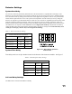
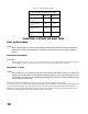
3. Two seconds after the test has commenced, the detector will have a current output that corresponds to the
quality of the vi reading obtained (see Table 4).
4. Release the manual vi test input. The detector will immediately return to normal operation if a vi fault is
not present.
5. If a vi fault is present, the current output will indicate 2mA.
Manual Check Procedure
The whole system should be checked periodically with a UV test lamp to make sure that the detectors are not
obstructed, that the area ‘seen’ by the detector has not changed and that there is no fault in the vi circuit.
CAUTION:
Secure all output loads connected to the fire detector to prevent unwanted activation.
1. Direct the UV test lamp into the detector viewing window.