
user manual
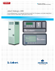


Two levels of microprocessor control systems are
available providing precise control and monitoring of
the critical space.
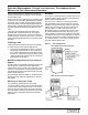
The Advanced Microprocessor is standard, and
the Advanced Microprocessor with Graphics is
optional. The main control functions are similar for
both controls.
The user must enter a three-digit password before
making changes.
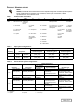
• Temperature Setpoint 65-85°F (18-29°C)*
• Temperature Sensitivity +1-10°F (0.6-5.6°C)
• Humidity Setpoint 20-80% RH*
• Humidity Sensitivity 1-30% RH
• High Temperature Alarm 35-90°F (2-32°C)
• Low Temperature Alarm 35-90°F (2-32°C)
• High Humidity Alarm 15-85% RH
• Low Humidity Alarm 15-85% RH
* The microprocessor may be set within these ranges;
however, the unit may not be able to control to
extreme combinations of temperature and humidity.
Factory set-up for Intelligent Control which uses
“fuzzy logic” and “expert systems” methods. Propor-
tional and Tunable PID are user selectable options.
• Compressor short cycle control: Prevents
compressor short-cycling and needless compres-
sor wear.
• System auto restart: The auto restart feature
will automatically restart the system after a
power failure. Time delay is programmable.
• Sequential Load Activation: On initial start-up
or restart after power failure, each operational
load is sequenced to minimize total inrush current.
• Hot Water / Econ-O-Coil Flush Cycles: Hot
water reheat coils and Econ-O-Coils are periodi-
cally flushed to prevent a build-up of contami-
nants.
• Temperature/Humidity Sensor Calibration:
The sensors may be calibrated from the front mon-
itor panel to insure that all units in the room are
similarly calibrated, assuring greater precision.
• Normal display: Includes present room temper-
ature and humidity, active functions (cooling,
heating, dehumidifying), and any alarms.
• Operating status: Displays each control opera-
tion in percent.
• Read analog inputs function: Displays the
present values of up to four analog inputs.
• Input diagnostics: Reviews inputs to the con-
trol system.
• Control board diagnostics: Initiates a self-test
of the control system.
• Output diagnostics: Tests major components
by turning them on and off from the control
panel. Includes: main fan, compressor, liquid line
solenoid valve, hot gas bypass valve, chilled
water or chilled GLYCOOL valve, R-5 relay,
reheat, hot water reheat valve, humidifier,
humidifier make-up valve, and common alarm.
• Alarm history log: The Advanced Microproces-
sor displays the 10 most recent alarms. The
Advanced Microprocessor with Graphics displays
the most recent 60 alarms. Both provide a time
and date stamp for each event
• Run time log: Displays run time and hours for
major components (also allows reset of run
hours) including compressors, GLYCOOL, fan,
humidifier, and reheat.
• Humidifier problem
• High head pressure
• Change filter
• Loss of air flow
• High temperature
• Low temperature
• High humidity
• Low humidity
• Compressor overload (opt)
• Main fan overload (opt)
• Low suction pressure
• Short cycle
• Loss of power
• Custom alarm (choose up to 4)
• Water under floor
• Smoke detected
• Standby GC pump on
• Loss of water flow
• Standby unit on
• User customized text
DISCONTINUED
PRODUC T