
Installation Instructions


Instruction Manual
D101329X012
1078 Actuator
October 2012
7
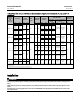
Table 5. Fisher 1061, 321, and 354 Actuator Size Selection and Specifications for Sizes 2A, 1A, B, C, D, and II-FA
(continued)
MANUAL
ACTUATOR
SIZE
(max output
torque)
SHAFT SIZE
POWER
ACTUATOR
GEAR
RATIO
HANDWHEEL
DIAMETER
MAXIMUM
TORQUE
(1)
WHEEL-RIM-FORCE
HANDWHEEL
TURNS FOR
ROTATION
For Maximum
Torque
For Less Than Maximum
Torque
Degrees
mm Inch Type Size mm Inch NSm LbfSin N Pounds N Pounds 60 90
B
(12,000 in.lbs)
31.8 1-1/4
354,
321
60,
60
40:1 610 24
1109 9815 308 68
Divide NSm
req'd by 3.6
Divide lbfSin
req'd by
144
6.7 10
38.1,
(44.4,
50.8)
1-1/2,
(1-3/4,
2)
1356 12,000 377 83
31.8 1-1/4
1061
40,
60, 68
1109 9815 308 68
38.1,
(44.4,
50.8)
1-1/2,
(1-3/4,
2)
1356 12,000 377 83
C
(18,000 in.lbs)
31.8 1-1/4
354,
321
60,
60
54:1 610 24
1109 9815 231 51
Divide NSm
req'd by 4.8
Divide lbfSin
req'd by
194
9 13.5
(44.4,
50.8)
(1-3/4,
2)
2034 18,000 424 93
31.8 1-1/4
1061
40,
60, 68
1109 9815 231 51
(44.4,
50.8)
(1-3/4,
2)
2034 18,000 424 93
D
(30,000 in.lbs)
(44.4,
50.8)
(1-3/4,
2)
354,
321
80,
80
64:1
762 30 2658 23,524 369 82
Divide NSm
req'd by 7.2
Divide lbfSin
req'd by
287
10.7 16
54,
63.5
57.2x
63.5
2-1/8,
2-1/2,
2-1/4x
2-1/2
914 36 3390 30,000 394 87
Divide NSm
req'd by 8.6
Divide lbfSin
req'd by
345
(44.4,
50.8)
(1-3/4,
2)
1061
80,
100
762 30 2658 23,524 369 82
Divide NSm
req'd by 7.2
Divide lbfSin
req'd by
287
54,
63.5
57.2x
63.5
2-1/8,
2-1/2,
2-1/4x
2-1/2
914 36 3390 30,000 394 87
Divide NSm
req'd by 8.6
Divide lbfSin
req'd by
345
II-FA
(60,000 in.lbs)
54,
63.5
2-1/8,
2-1/2
354,
321
80,
80
288:1
(2)
406 16 6301 55,762 400 90
Divide NSm
req'd by
15.7
Divide lbfSin
req'd by
619
48 72
54,
63.5
2-1/8,
2-1/2
1061
80,
100
1. Compare table value with torque requirements of the valve plus the torque required to compress the power actuator spring (from Fisher C atalog 14). Note that dynamic torque of the valve
may have a positive or negative effect on total torque required.
2. Has spur gear.
3. 2A 3/4 inch shaft will also mount on the 1061 size 40, 60, and 68.
4. Maximum torque of connection between power and manual actuator.
Installation
WARNING
Always wear protective gloves, c lothing, and eyewear when performing any installation operations to avoid personal
injury.
Check with your process or safety engineer for any additional measures that must be taken to protect against process
media.
If installing into an existing application, also refer to the WARNING at the beginning of the Maintenance section in this
instruction manual.