
Data Sheet


2500-249 Controllers and Transmitters
D200037X012
Product Bulletin
34.2:2500
July 2012
11
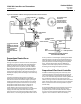
Figure 6. Schematic of Direct‐Acting Proportional‐Plus‐Reset Controller
PROPORTIONAL
BELLOWS
TORQUE TUBE SHAFT
SET POINT
ADJUSTMENT
RESET
VALVE
PROPORTIONAL
VALVE
EXHAUST
TO PROPORTIONAL
BELLOWS
TO RESET BELLOWS
SUPPLY PRESSURE
OUTPUT PRESSURE
NOZZLE PRESSURE
PROPORTIONAL
PRESSURE
RESET PRESSURE
WITH ARROW DOWN‐
RELIEVES ON
DECREASING OUTPUT
(OUTPUT AT SUPPLY
DURING SHUTDOWN)
DIFFERENTIAL
RELIEF VALVE
FROM
RELAY
PROPORTION
BAND ADJUSTMENT
RESET
ADJUSTMENT
CJ4081‐A
B2347‐2
E0792
PROPORTIONAL‐PLUS‐RESET CONTROL
WITH ANTI‐RESET WINDUP
Proportional Controller or
Transmitter
As long as the process remains constant, the displacer
will hold the torque tube shaft and attached flapper
steady in relation to the nozzle. The nozzle‐flapper
opening will be such as to permit pressure to bleed
from the nozzle as fast as it enters through the fixed
orifice of the relay, keeping the pressure loading on
the large relay diaphragm at the amount necessary to
balance the output pressure loading on the small relay
diaphragm.
A process variable change (such as a variation in
downstream demand that affects liquid outflow and
thus the level of the tank shown in figure 5) changes
the buoyant force acting on the displacer and moves
the flapper with respect to the nozzle. An increasing
buoyant force with direct action, or decreasing
buoyant force with reverse action, produces a
nozzle‐flapper restriction that increases nozzle
pressure on the large relay diaphragm. This opens the
supply end of the relay valve and increases relay
output pressure. But a decreasing buoyant force with
direct action, or increasing buoyant force with reverse
action, produces a nozzle‐flapper opening that bleeds
off nozzle pressure on the large relay diaphragm and
opens the exhaust end of the relay valve to let output
pressure (and thus actuator loading pressure) bleed
away. The relay diaphragm pressure differential
equalizes and a new output pressure is maintained
according to the change in displacer position.
Proportional‐Plus‐Reset Controller
All 2502 controllers (figure 6) have a two‐way reset
restriction valve that channels proportional pressure
into a reset bellows to oppose proportional bellows
action. This automatically slows the canceling effect of
any proportional action by a set amount per time
interval, as long as there is a deviation from the control
point. Action of this reset pressure occurs on a delayed
basis, and the reset valve can be adjusted to vary the
time of delay.
If a prolonged difference exists between the set point
and the process variable, output pressure with a
proportional‐plus‐reset controller will either drop to
zero or rise to the maximum delivered by the supply
regulator. This condition is called reset windup.