
Instruction Manual


Instruction Manual
D200138X012
3582, 582i, and 3583
February 2015
28
On some applications where the input signal span is comparatively small (as found with split‐range applications), the nozzle
adjustment may not be enough to set the proper starting point. Also, some difficulty may be experienced in keeping a valve
positioner from unloading when the input signal continues to increase above the split‐range.
For example, for a 0.2 to 0.6 bar (3 to 9 psig) input signal range, the input signal could increase to 1.0 bar (15 psig). Continued
bellows travel due to the increased input signal over the split‐range would drive the flapper into the nozzle. The impact could
possibly cause misalignment between the flapper and nozzle. Such a misalignment, in turn, could affect split‐range calibration.
In these cases, adjust the follower assembly screw in addition to the nozzle adjustment to obtain satisfactory results.
Note
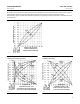
3582 valve positioners require a relatively small percentage of the instrument pressure span to obtain full valve travel. With the
travel pin set to equal the valve travel, the input signal change required to fully stroke the valve can be reduced to 33 percent of
normal input signal change. With the travel pin set to a value greater than the valve travel, the input signal change required to fully
stroke the valve can be reduced to a minimum of 20 percent of normal input signal change.
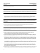
Changing Valve Positioner Action
Converting a 3582 valve positioner or 3582i valve positioner from direct acting (an increasing input signal, either
pneumatic or electrical, increases output pressure) to reverse acting (increasing input signal decreases output
pressure) or vice versa requires no additional parts. The position of the flapper assembly on the beam determines the
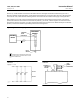
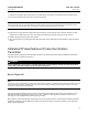
action. As shown in figure 15, the beam is divided into quadrants. The direct‐acting quadrant of the beam is labeled
DIRECT and the reverse‐acting quadrant is labeled REVERSE. To change the positioner action, simply move the flapper
assembly to the opposite quadrant of the beam. Perform the calibration procedures in the valve positioner calibration
section.
Figure 15. Partial View for Beam Leveling and Calibration
23A0308‐B
A6133
BEAM
PIVOT PIN
BEAM
NOZZLE
BEAM PIVOT
LOCKNUT
BELLOWS ASSEMBLY
LOCKNUT
BELLOWS
ASSEMBLY
PIVOT PIN
FLAPPER SETTING
ADJUSTMENT
FLAPPER
ASSEMBLY
FLAPPER ASSEMBLY
SCREW
SECTION A‐A
Changing Valve Stem Position Transmitter Action
Refer to figure 21 for key number locations unless otherwise indicated.
The flapper of the 3583 valve stem position transmitter is always positioned in the reverse‐acting quadrant as shown in
figure 19. To reverse the signal, reverse the cam as follows: