
Instruction Manual


Instruction Manual
D200149X012
3610J and 3620J Positioners
January 2015
30
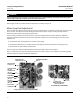
1. Unscrew the four captive cover screws, and remove the cover (key 41, figure 28).
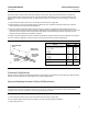
2. Loosen the reversing plate screw (key 49, figure 25), and adjust the reversing plate (key 23, figure 13) to expose the
letter R and cover the letter D.
3. For 3610J and 3620J positioners set up for 60 degree valve rotation, or 3611JP and 3621JP positioners set up for 11
mm (7/16‐inch) actuator travel or less, a change to reverse action also requires that the counter spring (key 125,
figure 25) be removed and discarded. To remove the counterspring, remove the machine screw (key 127,
figure 25), the spring seat (key 126, figure 25), and the counter spring (key 125, figure 25). Then replace the spring
seat and machine screw.
4. If using characterized cam B or C, refer to the Changing Cams procedures.
5. Perform the Zero and Span adjustment procedure.
6. Replace the cover.
Split‐Range Operation
CAUTION
Do not use bypass when the valve positioner is in split‐range operation. In this case, bypassing the valve positioner sends
the input signal directly to the actuator. Such a change will affect the desired operation and possibly upset the system. Use
bypass only when the input signal range is the same as the valve positioner range required for normal actuator operation.
Split‐range operation is possible with 3610J and 3620J positioners. With split‐range operation, the input signal from a
single control device is split between two or three control valves. The positioners will fully stroke the actuator with an
input signal span of 0.2 bar (3.2 psig) minimum to 2.0 bar (28.8 psig).
The zero adjustment of the positioner is continuously adjustable between 0.07 to 1.5 bar (1 and 22 psig).
Table 12 shows some typical split ranges for the positioners. Refer to tables 8 through 11 and figure 15 for the correct
range spring and range spring hole selection for the desired coarse span adjustment. Contact your Emerson Process
Management sales office, or the factory for input signal ranges not shown in table 12.
Note
The following is an example of range spring and range spring hole selection in tables 8 through 11. Assume a 0.2 to 0.6 bar (3 to 9
psig) input. This is equivalent to a span of 0.4 bar (6 psi) [0.6 bar - 0.2 bar = 0.4 bar (9 psig - 3 psig = 6 psi)]. Therefore for a 90
degree valve rotation and a span of 0.4 bar (6 psi), select a blue range spring. Place the range spring in hole number 2 on the
summing beam assembly.