Instruction Manual 3660 and 3661 Positioners D101402X012 January 2013 Fisherr 3660 and 3661 Positioners Contents Introduction . . . . . . . . . . . . . . . . . . . . . . . . . . . . . . . . . 2 Scope of Manual . . . . . . . . . . . . . . . . . . . . . . . . . . . . . 2 Description . . . . . . . . . . . . . . . . . . . . . . . . . . . . . . . . . 2 Specifications . . . . . . . . . . . . . . . . . . . . . . . . . . . . . . . 2 Educational Services . . . . . . . . . . . . . . . . . . . . . . . . .
3660 and 3661 Positioners January 2013 Instruction Manual D101402X012 Introduction Scope of Manual This instruction manual includes installation, operation, calibration, maintenance, and parts ordering information for Fisher 3660 and 3661 positioners. Refer to separate instruction manuals for information on the actuator and control valve.
Instruction Manual 3660 and 3661 Positioners D101402X012 January 2013 Table 1. Specifications Positioner Adjustments Available Configuration Span: J Adjustable up to 20 mm (0.75 inch) stem travel, or J Adjustable from 20 mm (0.75 inch) to 50 mm (2 inch) stem travel Zero: 0 to 100% Gain: 0.5 to 6% PB (proportional band)(3) Output Volume Damping: Loop dynamic response adjustment 3660: Single‐acting pneumatic valve positioner 3661: Single‐acting electro‐pneumatic valve positioner Input Signal 3660 J 0.
Instruction Manual 3660 and 3661 Positioners January 2013 D101402X012 Table 1. Specifications (Continued) Hazardous Area Classification for 3661 Conduit Connection for 3661 CSA—Intrinsically Safe, Type n, Non‐incendive 1/2 NPT (M20 or PG13 adaptors, optional) FM—Intrinsically Safe, Type n, Non‐incendive Maximum Valve Stem Travel ATEX—Intrinsically Safe, Type n (Gas Atmospheres Only) Two ranges: J 50 mm (2 inch) to 20 mm (0.75 inch) minimum; J 20 mm (0.
Instruction Manual D101402X012 3660 and 3661 Positioners January 2013 Installation Typically, a positioner is shipped with the actuator. If so, the factory mounts and calibrates the positioner and connects the positioner to actuator tubing. If the positioner is ordered separately from the actuator, perform the appropriate mounting procedure. Refer to the appropriate instruction manuals for actuator and valve installation procedures.
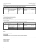
Instruction Manual 3660 and 3661 Positioners January 2013 D101402X012 Table 3. Hazardous Area Classifications for Fisher 3661 Positioner—CSA (Canada) Certification Body CSA Certification Obtained Intrinsically Safe Ex ia IIC T4/T5/T6 per drawing GE28591 Class I, II Division 1 GP A,B,C,D,E,F,G T4/T5/T6 per drawing GE28591 Entity Rating Vmax = 30 VDC Imax = 150 mA Pi = 1.25 W Ci = 0 nF Li = 0 mH Temperature Code Enclosure Rating T4 (Tamb ≤ 82°C) T5 (Tamb ≤ 62°C) T6 (Tamb ≤ 47°C) CSA Type 3 Encl.
Instruction Manual 3660 and 3661 Positioners D101402X012 January 2013 Type n The 3661 has an IP44 ingress protection: it is only intended to be installed in an area where a convenient protection is ensured against the entry of solid foreign bodies and liquids which may decrease the safety. Refer to table 5 for additional approval information and figure 30 for a typical ATEX/IECEx approval nameplate. Table 5.
3660 and 3661 Positioners Instruction Manual January 2013 D101402X012 Positioner Mounting Mounting on 1250, 1250R, 3024S, and GX Actuators During the following mounting procedures, refer to figures 3, 24, and 25 for key number locations. Figure 3 shows keys 64 through 78 and 101 through 104. Other key numbers are shown in either figure 24 for the 3660 positioner or figure 25 for the 3661 positioner. Two mounting methods are available, center‐bolt mounting and clamp mounting. 1.
Instruction Manual 3660 and 3661 Positioners D101402X012 January 2013 Figure 2. Mounting Configurations Input Signal Positioner Output Direct 0.2 to 1.0 bar (3 to 15 psig) 0.4 to 2.0 bar (6 to 30 psig) 4 to 20 mA Reverse 1.0 to 0.2 bar (15 to 3 psig) 2.0 to 0.4 bar (30 to 6 psig) 20 to 4 mA Up to 6.
Instruction Manual 3660 and 3661 Positioners January 2013 D101402X012 Figure 3. Positioner Mounting on Fisher 1250, 1250R, and 3024S Actuators CENTER BOLT MOUNT NIPPLE MOUNTED FILTER REGULATOR CLAMP MOUNT SECTION A‐A WEDGE NUT (KEY 104) FEEDBACK PLATE (KEY 68) FEEDBACK ADAPTOR (KEY 103) LOCKWASHER (K3Y 101) MACHINE SCREW (KEY 102) A A FEEDBACK LEVER ASSEMBLY FILTER REGULATOR SIZE 45 WITH TRAVEL BETWEEN 20 AND 30 mm (0.787 AND 1.
Instruction Manual 3660 and 3661 Positioners D101402X012 January 2013 Figure 4. Feedback Plate Orientation with Positioner Mounted on Fisher 1250, 1250R, and 3024S Actuators POSITIONER ACTUATOR LEG STEM CONNECTOR POSITIONER ACTUATOR LEG STEM CONNECTOR FEEDBACK PLATE FEEDBACK PLATE PILOT SHAFT FEEDBACK LEVER ASSEMBLY FOR SIZE 30 AND 34 ACTUATORS WITH TRAVEL BETWEEN 20 AND 30 mm (0.787 AND 1.
Instruction Manual 3660 and 3661 Positioners January 2013 D101402X012 other. If necessary, correct alignment by loosening the hex nuts (key 66) and moving the positioner on the actuator leg as required. f. Tighten the two hex nuts (key 66) to secure the positioner to the actuator leg. g. Install the feedback lever assembly and range spring. Mounting on Baumann Actuators During the following mounting procedures, refer to figures 2, 5, 6, 24, and 25.
Instruction Manual D101402X012 3660 and 3661 Positioners January 2013 Mounting on 657 and 667 Actuators During the following mounting procedures, refer to figures 7, 24, and 25 for key number locations. Figure 7 shows keys 69 and 70, 73 through 78, and 82 through 93. Other key numbers are shown in either figure 24 for the 3660 positioner or figure 25 for the 3661 positioner. 1. Determine the positioner mounting configuration from figure 2.
Instruction Manual 3660 and 3661 Positioners January 2013 D101402X012 Figure 7.
Instruction Manual 3660 and 3661 Positioners D101402X012 January 2013 Figure 8.
3660 and 3661 Positioners January 2013 Instruction Manual D101402X012 c. Tighten the machine screws and hex nuts (key 91 and 93) to secure the feedback arm (key 88) to the connector bracket (key 87). d. Tighten the hex head screws (key 69) to secure the connector bracket (key 87) to the actuator stem connector. 11. Install the feedback lever assembly and range spring.
Instruction Manual 3660 and 3661 Positioners D101402X012 Figure 9. Installing the Feedback Lever Assembly (Key 19) on the Positioner January 2013 Figure 10. Positioning Feedback Spring SPRING PIN FEEDBACK SPRING MUST HOOK AROUND SPRING PIN END OPPOSITE THE ZERO ADJUSTMENT SCREW ANTI‐ROTATING SLOT FEEDBACK SHAFT ZERO ADJUSTMENT FEEDBACK SPRING RETAINING SCREW (KEY 19P) COVER W7367 27B9999‐D A7224 7.
Instruction Manual 3660 and 3661 Positioners January 2013 D101402X012 Figure 11. Range Spring Installation Figure 12. Range Spring Alignment STRAIGHT PORTION OF SPRING RANGE SPRING FEEDBACK SHAFT LEVER ASSEMBLY BOSS SECTION A W7366 FEEDBACK SHAFT LEVER ASSEMBLY SLOT A5211 CAUTION Installation of the feedback lever assembly (key 19) prior to installation of the range spring (key 30) may result in damage to the lever assembly (key 17) flexures.
Instruction Manual D101402X012 3660 and 3661 Positioners January 2013 12. Move the pilot shaft (key 19A) to the approximate span position shown in table 8. Note To ensure proper positioner performance, make certain, after alignment and all tightening is completed, that there is clearance between the face of the pilot shaft and the feedback arm. 13. Install the feedback lever assembly cover (key 19T) with cover screw (key 19U). 14. Verify the positioner action.
Instruction Manual 3660 and 3661 Positioners January 2013 D101402X012 Figure 15. Typical Mounting Dimensions and Connections ACTUATOR CENTERLINE TO POSITIONER Type Size 657/667 1250 3024S Baumann GX Dimension X mm Inch 30 34 40 45/46 50/60 92.2 95.3 104.9 108.0 128.5 3.63 3.75 4.13 4.25 5.06 30 34 45 1.21 1.31 1.41 16in2 32in2 54in2 70in2 86.0 86.0 110.0 83.5 87.5 87.5 53.8 71.4 71.4 71.4 3.39 3.39 4.33 3.29 3.44 3.44 2.12 2.81 2.81 2.81 225 750 1200 81.0 81.0 81.0 3.19 3.19 3.
Instruction Manual 3660 and 3661 Positioners D101402X012 January 2013 Connect a clean, dry, oil‐free air source to the supply connection of the positioner. Use 3/8‐inch tubing or 1/4 NPT pipe for the supply line. A supply air filter or a filter regulator capable of removing particles 40 micrometers in diameter is recommended. The supply pressure should not exceed the following limits: 1. For the positioner, do not exceed the maximum pressure rating of 6.2 bar (90 psig). 2.
Instruction Manual 3660 and 3661 Positioners January 2013 D101402X012 Install the connectors and hardware between the 3660 or 3661 positioner and the actuator. 1. Before assembling the pipe nipple, pipe tee, pipe bushings, actuator piping, and connector body, apply sealant to all threads. Sealant is provided with the diagnostic connectors and hardware. 2. Turn the pipe tee to position the connector body and body protector for easy access when doing the diagnostic testing.
Instruction Manual 3660 and 3661 Positioners D101402X012 January 2013 Calibration The following calibration procedures are for the adjustment of the pneumatic positioner. For the 3661 positioner, there are no adjustments within the converter portion of the positioner. All adjustments are accomplished within the pneumatic portion of the positioner. WARNING During calibration the valve may move.
Instruction Manual 3660 and 3661 Positioners January 2013 D101402X012 Figure 19. Adjustment Locations (Equivalents of Pressures Shown in This Drawing are: 6 bar = 86 psig, 4 bar = 58 psig, and 1.4 bar = 20 psig) REFER TO INSTRUCTION MANUAL FOR POSITIONER ADJUSTMENT PROCEDURES ZERO NULL PUNKT D=DIRECT NORMAL CALIBRATION TOOL CALIBRATION WERKZEUG OUTIL DE REGLAGE TRAVEL HUB COURSE INCREASE TRAVEL SUPPLY ALIM. ZUL.
Instruction Manual 3660 and 3661 Positioners D101402X012 January 2013 15. Readjust the travel (span) adjustment to achieve correct actuator travel. Note When a travel (span) adjustment is made, there will be a zero shift. 16. Repeat steps 11 through 15 as necessary to achieve correct actuator travel. 17. Install the cover (key 19T) on the feedback lever assembly (key 19) with cover screw (key 19U). 18. Install the positioner cover (key 21) and secure with the machine screws (key 24).
Instruction Manual 3660 and 3661 Positioners January 2013 D101402X012 Table 8. Range Spring Selection for Baumann Actuators TYPE 3660 3661 VALVE STEM TRAVEL 0.2 to 1.0 bar (3 to 15 Psig) Input Signal 0.4 to 2.
Instruction Manual D101402X012 3660 and 3661 Positioners January 2013 upset the system. Use bypass operation only when the instrument signal range is the same as the positioner output range required for normal actuator operation. Labels on the bypass body assembly (key 41, figure 23), and a pointer on the bypass lever (key 42 in figure 23) indicate if the input signal from the instrument goes to the positioner or directly to the control valve actuator.
Instruction Manual 3660 and 3661 Positioners January 2013 D101402X012 Figure 21.
Instruction Manual 3660 and 3661 Positioners D101402X012 January 2013 D Vent the power actuator loading pressure and relieve any actuator spring precompression. D Use lock‐out procedures to be sure that the above measures stay in effect while you work on the equipment. D For 3661 positioners in intrinsically safe areas, current monitoring during operation must be with an approved meter for hazardous areas in order to avoid personal injury or property damage caused by an explosion or fire.
3660 and 3661 Positioners Instruction Manual January 2013 D101402X012 1. Release all pressure from the positioner. Disconnect the supply, instrument, and output tubing. For 3661 positioners, disconnect the input wires and conduit. 2. Unscrew the two captive cover screws and remove the cover (keys 24 and 21). Loosen the retaining screw (key 19P). 3. Pull the feedback lever assembly (key 19) out slightly to release the range spring tension, and remove the range spring (key 30). 4.
Instruction Manual 3660 and 3661 Positioners D101402X012 January 2013 6. With the input pressure set at either 1.4 or 2.4 bar (20 or 35 psig), check for leaks between the diaphragm assembly and the housing. 7. Refer to the Calibration section for the calibration procedure. Disassembling and Assembling Relay Components Before disassembling the relay components, remove the positioner from the actuator. Refer to the Removing the Positioner from the Actuator section.
3660 and 3661 Positioners Instruction Manual January 2013 D101402X012 8. Carefully lift the flapper spring at the location shown by key 10. Install the flapper (key 9) so that the desired letter (D or R for direct and reverse) is nearest the adjusting screw (key 18). When inserting the flapper, be sure the end of the flapper engages the grove in the end of the screw, and that the flapper spring (key 10) sets into the V‐notches of the flapper. 9.
Instruction Manual 3660 and 3661 Positioners D101402X012 January 2013 8. Install the three O‐rings (key 49) into the body assembly (key 41) and then carefully attach the body assembly to the positioner using the two cheese head screws (key 47). 9. Turn the bypass lever (key 42) to the appropriate POSITIONER or BYPASS position, and secure with the plastic wire tie (key 79). 10. Reconnect the supply, instrument and output tubing, and turn on pressure to the positioner.
Instruction Manual 3660 and 3661 Positioners January 2013 D101402X012 Parts Kits Description Repair Kits Description 3660 w/0.2 to 1 bar (3 to 15 psig) input R3660X00012 3661 R3660X00012 This kit contains keys 9, 26, 27, 28, 29, 43, 44, 45, 49, 95, and 97. Keys 43, 44, 45, and 49 are included in kit R3660X00012, but they are not used for the 3661. An additional O‐ring is also included in the kit for the I/P converter outlet.
Instruction Manual 3660 and 3661 Positioners D101402X012 January 2013 Figure 24.
Instruction Manual 3660 and 3661 Positioners January 2013 D101402X012 Figure 24. Fisher 3660 Positioner Assembly (continued) A A B C C B 51B3944‐F VIEW A‐A WITHOUT COVER Key Description 38* Output gauge (optional) Dual scale 0 to 2 Kg/cm2/0 to 30 psig 0 to 11 Kg/cm2/0 to 160 psig Triple scale 0 to 2 bar/0 to 0.2 MPa/0 to 30 psig 0 to 11 bar/0 to 1.
Instruction Manual 3660 and 3661 Positioners D101402X012 January 2013 Figure 25.
Instruction Manual 3660 and 3661 Positioners January 2013 D101402X012 Figure 25.
Instruction Manual 3660 and 3661 Positioners D101402X012 January 2013 Diagnostic Connections Key Description FlowScanner Valve Diagnostic System Hookup Includes pipe tees, pipe nipples, pipe bushings, connector bodies, and body protectors. 77 Cap screw, pl steel (2 req'd) For 657, 667, 1250, 1250R, 3024S and GX 78 Hex nut, zinc pl steel (2 req'd) For 657, 667, 1250, 1250R, 3024S and GX Note Part numbers are shown for recommended spares only.
Instruction Manual 3660 and 3661 Positioners January 2013 D101402X012 Description Key Description 3024C Actuator 84 68 69 70 71 72 85 86 87 88 89 90 91 92 93 U‐bolt, stainless steel (2 req'd) Sizes 50 and 60 Sizes 30, 34, 40, 45 and 46 Washer, stainless steel (4 req'd) Hex nut, stainless steel (4 req'd) Connector bracket, stainless steel Feedback arm, stainless steel Sealing washer Hex nut, stainless steel Machine screw, stainless steel (2 req'd) Washer, stainless steel (2 req'd)
Instruction Manual 3660 and 3661 Positioners D101402X012 January 2013 Figure 26.
Instruction Manual 3660 and 3661 Positioners January 2013 D101402X012 Loop Schematics/Nameplates for 3661 Positioner This section includes loop schematics required for wiring of intrinsically safe installations, as well as typical approvals nameplates. If you have any questions, contact your Emerson Process Management sales office. Figure 27.
Instruction Manual 3660 and 3661 Positioners D101402X012 January 2013 Figure 29. FM Loop Schematic for Fisher 3661 Positioner HAZARDOUS LOCATION NON-HAZARDOUS LOCATION INTRINSIC SAFETY CLASS I, II, III, DIV 1, GROUPS A,B,C,D,E,F,G CLASS I ZONE 0 AEx ia IIC NON-INCENDIVE CLASS I, DIV 2, GROUPS A,B,C,D FISHER TYPE: 3661 FM APPROVED BARRIER Vmax = 30 VDC Imax = 150 mA Ci = 0 nF Li = 0 mH Pi = 1.
3660 and 3661 Positioners January 2013 Instruction Manual D101402X012 Neither Emerson, Emerson Process Management, nor any of their affiliated entities assumes responsibility for the selection, use or maintenance of any product. Responsibility for proper selection, use, and maintenance of any product remains solely with the purchaser and end user. Fisher, Baumann, and FlowScanner are marks owned by one of the companies in the Emerson Process Management business unit of Emerson Electric Co.