
Instruction Manual

Instruction Manual
D101402X012
3660 and 3661 Positioners
January 2013
13
Mounting on 657 and 667 Actuators
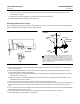
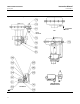
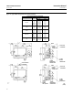
During the following mounting procedures, refer to figures 7, 24, and 25 for key number locations. Figure 7 shows
keys 69 and 70, 73 through 78, and 82 through 93. Other key numbers are shown in either figure 24 for the 3660
positioner or figure 25 for the 3661 positioner.
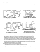
1. Determine the positioner mounting configuration from figure 2. The actuator size, actuator travel, and positioner
action must be known.
Note
The actuator bench set spring load must be released before removing the stem connector cap screws. Refer to the appropriate
actuator instruction manual for this procedure. After installing the positioner and mounting hardware, reset the actuator bench
set.
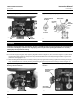
2. Attach the connector bracket (key 87) to the actuator stem connector using washers and cap screws (keys 70
and 69), but do not tighten the screws. Refer to figures 7 and 8 for the proper orientation of the connector bracket
with respect to the actuator stem connector. The face of the stem connector should be perpendicular to the legs of
the actuator yoke.
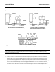
3. Refer to figure 8 for the feedback arm (key 88) location with respect to the connector bracket (key 87). Position the
feedback arm so that the pilot shaft (key 19A) will operate correctly in the slot of the feedback arm. For actuator
travels between 19 and 30 mm (0.75 and 1.18 inches), position the feedback arm so that the long portion of the
feedback arm slot, when fastened to the connector bracket, is closest to the positioner (see figure 8). For travels
greater than 30 mm (1.18 inches) reverse the feedback arm so the slot in the feedback arm is opposite the
positioner (see figure 8).
4. Attach the feedback arm (key 88) to the connector bracket (key 87) using machine screws, washers and hex nuts
(keys 91, 92 and 93), but do not tighten the hex nuts.
5. Unscrew the two machine screws (key 24), and remove the positioner cover (key 21).
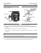
6. As shown in figure 5, a thin knockout section is cast across the mounting hole in the housing. Check to make certain
that this knockout section has been removed. If the knockout section has not been removed, use a punch to knock
it out.
7. Set the actuator at mid‐travel using a manual loading regulator.
8. Install the stud clamp (key 83) in the mounting bracket (key 82). Place the mounting bracket against the outside of
the actuator leg. Attach the two U‐bolts (key 84) and the mounting bracket to the actuator leg using washers and
hex nuts (key 85 and 86), but do not tighten the nuts. Depending on the positioner action, it may be necessary to
straddle the travel indicator scale located on the inside of the actuator leg.
Note
Do not install the range spring in the following step. Feedback lever assembly (key 19) installation in the next step is only
temporary to permit verifying alignment.