
Instruction Manual

Instruction Manual
D101402X012
3660 and 3661 Positioners
January 2013
15
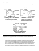
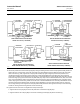
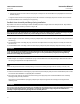
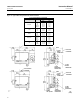
Figure 8. Feedback Arm Orientation with Positioner Mounted on Fisher 657 and 667 Actuators
B2256‐1
SIZES 30 THROUGH 40 ACTUATORS WITH
TRAVEL UP TO 30 mm (1.18 INCHES)
SIZES 30 THROUGH 40 ACTUATORS WITH
TRAVEL GREATER THAN 30 mm (1.18 INCHES)
SIZES 45 THROUGH 60 ACTUATORS WITH
TRAVEL GREATER THAN 30 mm (1.18 INCHES)
ACTUATOR STEM
PILOT SHAFT
PILOT SHAFT
PILOT SHAFT
PILOT SHAFT
POSITIONER
POSITIONER
POSITIONER
POSITIONER
STEM CONNECTOR
STEM
CONNECTOR
STEM CONNECTOR
STEM CONNECTOR
ACTUATOR STEM
ACTUATOR STEM
ACTUATOR STEM
CONNECTOR
BRACKET
CONNECTOR
BRACKET
CONNECTOR
BRACKET
CONNECTOR
BRACKET
CONNECTOR
BRACKET
CONNECTOR
BRACKET
FEEDBACK LEVER
ASSEMBLY
FEEDBACK LEVER ASSEMBLY
FEEDBACK
LEVER ASSEMBLY
FEEDBACK LEVER
ASSEMBLY
FEEDBACK
ARM
FEEDBACK
ARM
FEEDBACK
ARM
FEEDBACK ARM
VALVE STEM
VALVE STEM
FEEDBACK
ARM
ACTUATOR LEG
ACTUATOR LEG
ACTUATOR LEG
ACTUATOR LEG
VIEW A
VIEW B
A
A
B
B
SIZES 45 THROUGH 60 ACTUATORS WITH
TRAVEL UP TO 30 mm (1.18 INCHES)
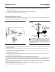
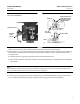
9. Attach the positioner to the stud clamp (key 83) using the sealing washer and hex nut (keys 89 and 90), but do not
tighten the nut. Visually center the center line of the slot in the feedback arm (key 88) with the center line of the
hole in the housing. Then, tighten the nuts (keys 90 and 86) only tight enough to prevent the positioner and
mounting bracket from moving on the actuator leg. Locate the feedback lever assembly (key 19) so it may be
temporarily installed into the positioner housing (key 1) and the feedback arm (key 88) to verify alignment. Do not
install the range spring at this time. Place the pilot shaft (key 19A) in the slot of the feedback arm, and, at the same
time, insert the feedback shaft in the hole of the positioner housing. Depress the feedback lever assembly inward
until it stops against the housing. Make certain the slots in both the feedback lever assembly and feedback arm are
horizontal and that the feedback lever assembly and the feedback arm are parallel with each other. If necessary,
correct alignment by loosening the hex nuts (keys 86 and 90) and either moving the stud clamp in the mounting
bracket or moving the mounting bracket on the actuator leg.
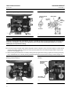
10. Tighten the nuts that were not tightened in the previous steps.
a. Tighten the hex nut (key 90) to secure the positioner to the stud clamp (key 83).
b. Tighten the four hex nuts (key 86) to secure the mounting bracket (key 82) to the actuator leg.