
Instruction Manual

Instruction Manual
D101402X012
3660 and 3661 Positioners
January 2013
17
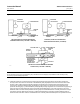
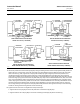
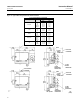
Figure 9. Installing the Feedback Lever Assembly
(Key 19) on the Positioner
RETAINING
SCREW
(KEY 19P)
ANTI‐ROTATING SLOT
W7367
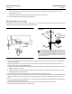
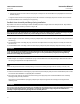
Figure 10. Positioning Feedback Spring
ZERO
ADJUSTMENT
COVER
FEEDBACK
SHAFT
SPRING PIN
FEEDBACK SPRING
FEEDBACK SPRING MUST
HOOK AROUND SPRING
PIN END OPPOSITE THE
ZERO ADJUSTMENT
SCREW
27B9999‐D
A7224
7. Tighten the retaining screw (key 19P) until the screw engages the anti‐rotating slot so that the bushing does not
rotate, but leave the screw loose enough so that the bushing can slide freely into the housing.
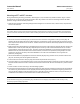
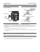
8. Refer to figures 11 and 12. Select the appropriate range spring (key 30) from tables 7 and 8. Place the range spring
in the positioner so that one end of the spring is fully in the lever assembly slot. Next, rotate the feedback lever
assembly so that:
D the other end of the range spring aligns with the slot in the feedback shaft, and
D the pilot shaft (key 19A) is either above or below the actuator feedback plate or engages the slot in the feedback
arm (key 88).
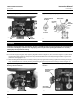
Note
The feedback lever assembly bushing will no longer slide freely in the housing after it is placed in the normal operating position
due to the side loading of the retaining screw (key 19P) on the anti‐rotating slot.
9. Center the range spring (key 30) in the lever assembly (key 17) and feedback shaft slots; then push the feedback
lever assembly bushing into the housing far enough so that the spring is retained without holding it.