
Instruction Manual


Instruction Manual
D101402X012
3660 and 3661 Positioners
January 2013
21
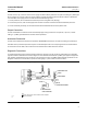
Connect a clean, dry, oil‐free air source to the supply connection of the positioner. Use 3/8‐inch tubing or 1/4 NPT pipe
for the supply line. A supply air filter or a filter regulator capable of removing particles 40 micrometers in diameter is
recommended. The supply pressure should not exceed the following limits:
1. For the positioner, do not exceed the maximum pressure rating of 6.2 bar (90 psig).
2. For actuator pressure, refer to the appropriate actuator instruction manual for maximum allowable pressures.
3. For the valve body assembly, do not exceed the maximum allowable thrust of the specific valve.
Output Connection
Connect the OUTPUT connection to the actuator diaphragm casing connection. Use 3/8‐inch, 1/4‐inch, or 6 mm
tubing, or 1/4 NPT pipe between the actuator and the positioner.
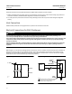
Instrument Connection
Connect the control device output to the positioner INSTRUMENT connection. Use 3/8‐inch tubing to 1/4 NPT pipe.
The 3661 electro‐pneumatic positioner requires a 4-20 milliampere DC current input signal from the control device.
For connections to the 3661, refer to the Electrical Connections for 3661 Positioners section.
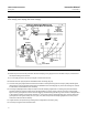
Diagnostic Connections
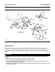
To support diagnostic testing of valve/actuator/positioner packages, special connectors and hardware are available.
Typical connector installations are shown in figure 16. The hardware used includes 1/4 NPT pipe nipples and pipe tees
with 1/8 NPT pipe bushings for the connectors. The connectors consist of 1/8 NPT bodies and body protectors. If the
diagnostic connectors are ordered for a positioner with gauges, 1/8‐inch stems are also included.
Figure 16. FlowScannert Valve Diagnostic System Connections
12B8052‐A
A6084
BODY PROTECTOR
BODY
PIPE BUSHING
PIPE TEE
1 INCH LONG PIPE NIPPLE
4 INCH LONG
PIPE NIPPLE
GAUGE
STEM
PROVIDED WHEN
GAUGE IS SPECIFIED
NOTE:
1 PIPE TEE, NIPPLE, BUSHING, BODY AND PROTECTOR NOT REQUIRED
FOR THE 3661 POSITIONER