
Instruction Manual


Instruction Manual
D101402X012
3660 and 3661 Positioners
January 2013
23
Calibration
The following calibration procedures are for the adjustment of the pneumatic positioner. For the 3661 positioner,
there are no adjustments within the converter portion of the positioner. All adjustments are accomplished within the
pneumatic portion of the positioner.
WARNING
During calibration the valve may move. To avoid personal injury and property damage caused by the release of pressure or
process fluid, provide some temporary means of control for the process.
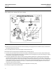
Refer to figure 24 (3660) or figure 25 (3661) for key number locations unless otherwise indicated. Adjustment
locations are shown in figure 19.
1. If mounting a new positioner on an actuator or if the positioner action has not been changed, do not perform
steps 2 through 7.
2. If the positioner action has been changed or if the positioner has had maintenance performed on it, complete
steps 3 through 17.
3. If the cover (key 21) has not been removed, unscrew the two machine screws (key 24), and remove the cover.
4. Release all pressure from the positioner. Disconnect the positioner output tubing to the actuator. If the positioner is
equipped with an output gauge, plug the positioner output connection. If the positioner is not equipped with an
output gauge, provide a gauge to monitor positioner output and connect it to the positioner output connection.
5. Set the supply pressure to the required setting. Set the gain (proportional band) adjustment screw at a nominal
value by turning it clockwise until it stops, and then turning it counterclockwise 1 turn.
Note
Adjusting the gain (PB) adjustment changes the nozzle flapper relationship. This nozzle flapper change affects the
actuator/positioner response time.
Note
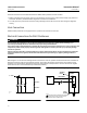
To improve holding of the calibration tool as used in step 6, the actuator may be used to create the load (manual pressure) by
winding up the positioner range spring. The direction of windup, looking at the spring from outside the housing, must be
clockwise. This windup will create a torsional force over the input diaphragm through the lever assembly. The spring is
automatically wound up in two of the positioner/actuator mounting positions when the loading pressure is removed. These are
left‐hand mounting on a spring‐to‐close actuator and right‐hand mounting on a spring‐to‐open actuator (refer to figure 2). In the
other two mounting positions, the actuator must be pressurized to 100 percent input to create the spring holding force.
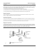
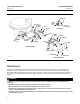
6. Remove the calibration tool (key 6) from the cover. Place the calibration tool between the lever assembly (key 17)
and the input diaphragm assembly (key 28). When making the following adjustment, apply manual pressure to the
lever assembly over the input diaphragm assembly to hold the calibration tool in place. Loosen the lock nut
(key 57), and turn the adjusting screw (key 18) until the output is 50% ± 10% of supply pressure. For example, if
supply pressure is 2.4 bar, set the output to 1.2 bar ± 0.24 bar.
7. Lock the adjusting screw (key 18) with the lock nut (key 57). After the adjustment is complete, remove the
calibration tool and replace it in the positioner cover.