
Instruction Manual


Instruction Manual
D101402X012
3660 and 3661 Positioners
January 2013
25
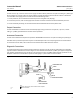
15. Readjust the travel (span) adjustment to achieve correct actuator travel.
Note
When a travel (span) adjustment is made, there will be a zero shift.
16. Repeat steps 11 through 15 as necessary to achieve correct actuator travel.
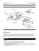
17. Install the cover (key 19T) on the feedback lever assembly (key 19) with cover screw (key 19U).
18. Install the positioner cover (key 21) and secure with the machine screws (key 24). Make sure the Fisher logo reads
correctly and the vent is pointing downward.
Split‐Range Operation
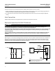
3660 and 3661 positioners can be used for split‐range operation with the instrument input signal from a single
controller or another instrument split between two or three control valves. Tables 7 and 8 show some typical split
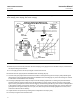
ranges for the positioners. To change from a full range to a split range, change the range spring (key 30, figure 24 or
25) to the appropriate spring shown in the tables. Complete the Changing Range Spring portion of the Maintenance
section. Refer to tables 7 and 8 for valve stem travel available with split range operation.
Table 7. Range Spring Selection for Fisher Actuators
TYPE 3660 3660 3661
VALVE STEM TRAVEL
WHEN USING
3660 AND 3661
RANGE SPRING
PART NUMBER
(KEY 30)
Split
0.2 to 1.0 bar
(3 to 15 psig)
Input Signal
0.4 to 2.0 bar
(6 to 30 psig)
Input Signal
4 to 30 mA DC
Input Signal
Bar Psig Bar Psig mm Inches
One Way 1:1 0.2 to 1.0 3 to 15 0.4 to 2.0 6 to 30 4 to 20 19 to 50 0.75 to 2.0 11B3880X012
Two Way 2:1
0.2 to 0.6
0.6 to 1.0
3 t0 9
9 to 15
0.4 to 1.2
1.2 to 2.0
6 to 18
18 to 30
4 to 12
12 to 20
19 to 50 0.75 to 2.0 11B3881X012
Three Way 3:1
0.2 to 0.5
0.5 to 0.8
0.8 to 1.0
3 to 7
7 to 11
11 to 15
0.4 to 1.0
1.0 to 1.5
1.5 to 2.0
6 to 14
14 to 22
22 to 30
4 to 9.33
9.33 to 14.66
14.66 to 20
15 to 33.3 0.591 to 1.311 11B3881X012