
Instruction Manual


Instruction Manual
D101402X012
3660 and 3661 Positioners
January 2013
28
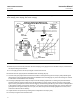
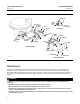
Figure 21. Operational Schematic
FLAPPER
DIRECT
ACTING
PIVOT
REVERSE
ACTING PIVOT
NOZZLE
OUTPUT
RANGE
SPRING
RELAY
GAIN ADJA
A
FEEDBACK
PLATE
FEEDBACK
LEVER
PILOT
SHAFT
INPUT MODULE
BEAM
PIVOT
SUPPLY
RANGE
SPRING
RELAY
GAIN ADJ
SUPPLY
A
A
INPUT SIGNAL
I/P CONVERTER
INPUT MODULE
BEAM
PIVOT
SECTION A‐A
3660 POSITIONER
3661 POSITIONER
31B3960‐C
B2152‐4
Maintenance
Positioner parts are subject to normal wear and must be inspected and replaced as necessary. The frequency of
inspection and replacement depends upon the severity of service conditions. The following procedure describes
disassembly and reassembly of the positioner. When inspection or repairs are required, disassemble only those parts
necessary to accomplish the job. When reassembly is complete, make adjustments as described in the Calibration
section.
WARNING
Avoid personal injury or property damage from sudden release of process fluid. Before performing any Maintenance
procedures:
D Always wear protective clothing, gloves, and eyewear to avoid personal injury.
D Do not remove the actuator from the valve while the valve is still pressurized.
D Disconnect any operating lines providing air pressure, electric power, or a control signal to the actuator. Be sure the
actuator cannot suddenly open or close the valve.
D Use bypass valves or completely shut off the process to isolate the valve from process pressure. Relieve process pressure
on both sides of the valve.