Instruction Manual 3710 and 3720 Positioners D101728X012 January 2015 Fisherr 3710 and 3720 Valve Positioners and 3722 Electro-Pneumatic Converter Contents Introduction . . . . . . . . . . . . . . . . . . . . . . . . . . . . . . . . . 2 Scope of Manual . . . . . . . . . . . . . . . . . . . . . . . . . . . . . 2 Description . . . . . . . . . . . . . . . . . . . . . . . . . . . . . . . . . 2 Positioner to Actuator Mountings List . . . . . . . 5 Specifications . . . . . . . . . . . . . . . . . . . . . . .
Instruction Manual 3710 and 3720 Positioners D101728X012 January 2015 Contents (cont'd) Maintenance . . . . . . . . . . . . . . . . . . . . . . . . . . . . . . . . Positioner Maintenance . . . . . . . . . . . . . . . . . . . . . . Replacing the Standard or Beacon Indicator . Removing the 3722 Converter . . . . . . . . . . . . Removing the Positioner . . . . . . . . . . . . . . . . . Removing the Feedback Arm Assembly . . . . . Disassembling the Feedback Arm Assembly and Span Adjuster Assembly . . . . .
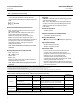
Instruction Manual 3710 and 3720 Positioners D101728X012 January 2015 Table 1. Specifications Steady‐State Air Consumption(4) Available Configurations 3710: J Single‐ or J double‐acting pneumatic rotary valve positioner 3720: J Single‐ or J double‐acting electro‐pneumatic rotary valve positioner consisting of a 3710 with a 3722 attached 3722: An electro‐pneumatic converter that converts a 4-20 mA DC input signal to a 0.2 to 1.
Instruction Manual 3710 and 3720 Positioners D101728X012 January 2015 Table 1.
Instruction Manual 3710 and 3720 Positioners D101728X012 January 2015 Table 3. Input Signal Range INPUT SIGNAL RANGE POSITIONER 3710 w/3 to 15 psig span adj. ass'y (no color coding) 3710 w/6 to 30 psig span adj. ass'y (red color coding) Pneumatic Electronic J 0.2 to 1.0 bar (3 to 15 psig) J 0.2 to 0.6 bar (3 to 9 psig) and 0.6 to 1.0 bar (9 to 15 psig), split‐ranging J 0.4 to 2.0 bar (6 to 30 psig) J 0.4 to 1.2 bar (6 to 18 psig) and 1.2 to 2.
Instruction Manual 3710 and 3720 Positioners D101728X012 January 2015 Table 4.
Instruction Manual 3710 and 3720 Positioners D101728X012 January 2015 D Use lock‐out procedures to be sure that the above measures stay in effect while you work on the equipment. D Do not open where an explosive dust atmosphere is present. D Check with your process or safety engineer for any additional measures that must be taken to protect against process media. WARNING The positioner can provide full supply pressure to any connected equipment.
Instruction Manual 3710 and 3720 Positioners D101728X012 January 2015 Table 5.
Instruction Manual 3710 and 3720 Positioners D101728X012 January 2015 Special Conditions for Safe Use Intrinsically Safe This equipment is intrinsically safe and can be used in potentially explosive atmospheres. The electrical parameters of certified equipment which can be connected to the device must not exceed one of these following values: U0 ≤ 30 VDC; I0 ≤ 150 mA; P0 ≤ 1.
Instruction Manual 3710 and 3720 Positioners D101728X012 January 2015 IECEx Conditions of Certification Intrinsically Safe WARNING Substitution of components may impair intrinsic safety. -40_C ≤ Ta ≤ +82_C; T6 (Ta ≤ +47_C); T5 (Ta ≤ +62_C); T4 (Ta ≤ +82_C) Entity Parameters: Ui = 30 V, li = 150 mA, Pi = 1.25 W, Ci = 0 nF, Li = 0 mH Flameproof WARNING Disconnect power before opening. -40_C ≤ Ta ≤ +82_C; T5 (Ta ≤ +82_C) Type n WARNING Disconnect power before opening.
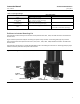
Instruction Manual 3710 and 3720 Positioners D101728X012 January 2015 Installation To change an existing 3710 positioner into a 3720 positioner, install a 3722 electro‐pneumatic converter (figure 3). The 3722 electro‐pneumatic converter mounts over the input and supply connections of the 3710 positioner. Figure 3. Fisher 3722 Electro‐Pneumatic Converter SUPPLY CONNECTION EXTERNAL GROUNDING SCREW W6145 1/2‐NPT CONDUIT CONNECTION 1. Be sure all safety procedures have been followed.
3710 and 3720 Positioners Instruction Manual January 2015 D101728X012 If the proper mounting holes are present, perform the following mounting procedure and then follow the calibration procedures in this instruction manual. Refer to the appropriate instruction manuals for actuator and valve mounting procedures. WARNING Avoid personal injury from sudden release of process pressure.
Instruction Manual 3710 and 3720 Positioners D101728X012 January 2015 Figure 4.
3710 and 3720 Positioners Instruction Manual January 2015 D101728X012 1. See figure 5 for a typical actuator. Remove the actuator travel indicator machine screws, travel indicator, and actuator cover cap screws. Note When removing the actuator cover plate, take care not to change the position of the rod end bearing on the end of the turnbuckle inside the actuator housing. 2. If necessary, install a new cover plate. a. Remove the existing cap screws and actuator cover plate from the actuator housing.
Instruction Manual 3710 and 3720 Positioners D101728X012 January 2015 Figure 5. Typical Piston Actuator (Fisher 1061) W6146‐1 W6147‐1 TIE BAR, MOUNTING PLATE REMOVED REAR VIEW, POSITIONER BASE PLATE, AND MOUNTING AREA Figure 6.
Instruction Manual 3710 and 3720 Positioners D101728X012 January 2015 Installing the 3710 or 3720 Pneumatic Positioner on Size 25 or 50 585 and 585R Actuators Refer to figures 7, 8, and 9 for key number locations unless noted otherwise. Figure 7.
Instruction Manual 3710 and 3720 Positioners D101728X012 January 2015 Figure 8. Drive Stud and Roller Bearing Assembly Figure 9. Drive Stud Bracket with Drive Stud and Roller Bearing Assembly DRIVE STUD BRACKET (KEY 98) DRIVE STUD (KEY 95) ROLLER BEARING (KEY 101) E‐RING (KEY 102) LOCK WASHER (KEY 100) FLAT WASHER (KEY 1103) DRIVE STUD AND ROLLER BEARING HEX NUT (KEY 96) Note Before performing the next step, position the valve plug stem at the lower end of its travel.
Instruction Manual 3710 and 3720 Positioners D101728X012 January 2015 15. Make sure the cam locknut (key 37, figure 31) is loose, then stroke the valve/actuator to mid‐travel. Adjust the drive stud location vertically so that the feedback lever is perpendicular to the stem. Tighten the hex nut attached to the drive stud. 16. Refer to figure 11. Adjust the position of the drive stud bracket so that the center of the roller bearing aligns with the appropriate travel mark on the feedback lever. 17.
Instruction Manual 3710 and 3720 Positioners D101728X012 January 2015 Figure 12. Connections OUTPUT CONNECTIONS INPUT (SUPPLY) CONNECTION TOP VIEW VENT INPUT CONNECTIONS M20 CABLE GLAND RIGHT SIDE VIEW VENT OPENING RIGHT SIDE VIEW 34B0693‐A B2386‐1 3720 POSITIONER REAR VIEW 3710 POSITIONER The conduit connection to the converter is 1/2‐14 NPT. The positioner does not have a remote vent connection.
3710 and 3720 Positioners Instruction Manual January 2015 D101728X012 Supply pressure must not exceed the following limits: D For the positioner, do not exceed the maximum pressure rating of 10.3 bar (150 psig). D For actuator pressure, refer to the appropriate actuator instruction manual for maximum allowable pressures. D For the valve body assembly, do not exceed the maximum allowable torque or thrust of the specific valve. Output Connections See figure 12.
Instruction Manual 3710 and 3720 Positioners D101728X012 January 2015 Figure 13. Mounting the Positioner Base Plate with Purge Tube PURGE TUBE (KEY 58) O‐RINGS (KEY 59) LONG‐BLADED SCREW DRIVER THROUGH VENT W6073 The positioner does not have an external vent connection. A unit exhausts actuator pressure through a screened hole (vent opening, figure 12) located in the positioner base plate. Do not restrict the vent opening.
3710 and 3720 Positioners Instruction Manual January 2015 D101728X012 If the 1/4 NPT vent connection is available, a vent line can be installed from the actuator. However, the valve/actuator/positioner assembly is not airtight. Maintain adequate ventilation and observe other safety measures. For help in selecting the purge option for positioner/ actuator combinations, contact your Emerson Process Management sales office.
Instruction Manual 3710 and 3720 Positioners D101728X012 January 2015 Use the 1/2‐14 NPT conduit connection for field wiring installation. Refer to figures 14 and 15 when connecting field wiring from the control device to the converter. Connect the positive wire from the control device to the converter's positive ( + ) terminal and the negative wire from the control device to the converter's negative ( ‐ ) terminal. Do not overtighten the terminal screws. Maximum torque is 0.45 Newton‐meters (0.
Instruction Manual 3710 and 3720 Positioners D101728X012 January 2015 Figure 16.
Instruction Manual 3710 and 3720 Positioners D101728X012 January 2015 Calibration The following calibration procedures are for the 3710 pneumatic positioner adjustment. For the 3720 electro‐pneumatic positioner, there are no adjustments within the 3722 converter portion of the positioner. All adjustments are accomplished within the pneumatic portion of the positioner. WARNING During calibration the valve will move.
Instruction Manual 3710 and 3720 Positioners D101728X012 January 2015 Zero and Span Adjustments See figure 19. Figure 19.
Instruction Manual D101728X012 3710 and 3720 Positioners January 2015 Tighten the zero adjustment locknut before proceeding to step 5. 5. Slowly increase the input signal until the input reaches the maximum input signal. Observe the actuator travel and valve position as the input increases. Determine the actuator/valve position at the maximum input signal. 6.
Instruction Manual 3710 and 3720 Positioners D101728X012 January 2015 Figure 20. Standard Indicator 2 FEEDBACK SHAFT (CAM SHAFT) (KEY 38) 1 INDICATOR (KEY 15) INDICATOR SCALE (KEY 14) NOTES: 1 RETAINING RING (E‐CLIP) (KEY 12) IS NOT SHOWN. 2 THE SHAFT OF THE INDICATOR (KEY 15) PASSES THROUGH THE POSITIONER COVER AND FITS OVER THE END OF THE FEEDBACK SHAFT (CAM SHAFT) (KEY 38). W6061 3. Inspect the indicator, pointer, and scale. Make sure the proper valve position is shown.
Instruction Manual 3710 and 3720 Positioners D101728X012 January 2015 D Vent the actuator loading pressure. D Use lock‐out procedures to be sure that the above measures stay in effect while you work on the equipment. D Check with your process or safety engineer for any additional measures that must be taken to prevent against process media. Single‐Acting/Double‐Acting See figure 21 for positioner output connections. See figure 23 for the positioner schematic. Figure 21.
3710 and 3720 Positioners Instruction Manual January 2015 D101728X012 See figure 21. 1. Turn off supply pressure. Reverse the piping connections between the actuator and the positioner output connections (OUTPUT A and OUTPUT B). D For single‐acting output, disconnect piping from OUTPUT B. Unplug OUTPUT A and connect the piping to it. Plug OUTPUT B. D For double‐acting output, disconnect piping from both positioner outputs. Connect piping from OUTPUT A to OUTPUT B.
Instruction Manual 3710 and 3720 Positioners D101728X012 January 2015 D Vent the actuator loading pressure. D Use lock‐out procedures to be sure that the above measures stay in effect while you work on the equipment. D Check with your process or safety engineer for any additional measures that must be taken to prevent against process media. 1. Turn off supply pressure. Release actuator pressure. Remove the positioner cover assembly (key 7). Note Handle the spool valve body and spool with care.
Instruction Manual 3710 and 3720 Positioners D101728X012 January 2015 Figure 22. Spool Valve and Summing Beam SPOOL VALVE ASSY SPOOL RELIEF SPOOL HEAD SPOOL HEAD SPOOL FLEXURE CLEARANCE SPOOL FLEXURE LARGER VIEW OF SPOOL HEAD SUMMING BEAM ASSY A6044 Changing the Span Adjuster Assembly (To Change Positioner Input Range) The span adjuster assembly (key 4) consists of the span adjustment knob, span adjustment shaft (threaded rod), range spring, and washer.
Instruction Manual 3710 and 3720 Positioners D101728X012 January 2015 6. Inspect the zero adjustment pivot (key 32). Be sure it rotates freely. If necessary, replace the zero adjustment pivot. Also, if necessary, replace the feedback arm assembly (key 21) and cam roller (key 23), following the instructions given in this manual. 7. Install the new span adjuster assembly by sliding the span adjustment shaft (threaded rod) through the zero adjustment pivot.
3710 and 3720 Positioners January 2015 Instruction Manual D101728X012 determined by the location or rise of the cam which is attached to the feedback shaft. When the two opposing forces are equal or at a steady state, the summing beam holds the spool in a neutral position. At steady state, a small flow of air passes from supply through both outputs of the spool valve to the actuator, holding the actuator at a constant position.
Instruction Manual 3710 and 3720 Positioners D101728X012 January 2015 The optional beacon indicator uses a retaining ring (e‐clip) (key 12) on the outside of the positioner cover. The retaining ring holds the extension shaft. After removing the beacon indicator, remove the external retaining ring to free the extension shaft. 3. Remove the internal or external retaining ring that holds the indicator/extension shaft. Remove the indicator/extension shaft from the positioner cover. 4.
3710 and 3720 Positioners January 2015 Instruction Manual D101728X012 4. Inspect the feedback tie bar (key 42) attached to the actuator hub. If necessary, unscrew the machine screws (key 47) and remove the tie bar. Removing the Feedback Arm Assembly 1. Unscrew the cam locknut (key 37) and remove the cam (key 36). Note The zero adjustment locknut and zero adjustment knob are identical parts, key 35. 2.
Instruction Manual 3710 and 3720 Positioners D101728X012 January 2015 Disassembling the Feedback Arm Assembly and Span Adjuster Assembly Note The zero adjustment locknut and zero adjustment knob are identical parts, key 35. Note To identify the span adjuster assembly for 0.4 to 2.0 bar (6 to 30 psig) input range, red color coding appears on the range spring. 1. Remove the feedback arm assembly and flanged bearing (key 22) from the feedback pivot in the positioner base plate.
Instruction Manual 3710 and 3720 Positioners D101728X012 January 2015 Figure 26. Spool Valve Body and Spool SPOOL VALVE BODY SPOOL HEAD W5917 SPOOL 1. Unscrew the two machine screws (key 3) that hold the spool valve (key 1) onto the action block (key 28). Remove the spool valve, taking care when separating the spool from the flexure on the summing beam. 2. Inspect the three O‐rings (key 2) found between the spool valve and the action block. Remove and replace the O‐rings, if necessary.
Instruction Manual D101728X012 3710 and 3720 Positioners January 2015 4. See figure 27. Separate the summing beam assembly from the input module by removing one of the two machine screws (key 20) that hold the flexure retainers which join the summing beam flexure to the input module housing. Figure 27. Separating the Summing Beam Assembly from the Input Module W5913 Replacing the Input Module Diaphragm See figure 28. 1.
Instruction Manual 3710 and 3720 Positioners D101728X012 January 2015 Figure 28. Input Module Diaphragm and Diaphragm Housing Figure 29. Assembly of Input Module A6043 W5915 Assembling the Input Module and Summing Beam Assembly 1. Position the summing beam on the input module housing. Place the flexure over the alignment pins extending from the summing beam and input module. Secure the flexure by placing the two flexure retainers over the alignment pins extending through the flexure.
Instruction Manual 3710 and 3720 Positioners D101728X012 January 2015 4. See figure 30. Properly position the input module and summing beam assembly on the positioner base plate using the alignment pins on the input module. If the spool valve (key 1) has not been removed, use care when positioning the input module and summing beam assembly. Make sure the spool extending from the spool valve body properly engages the spool flexure. Figure 30.
3710 and 3720 Positioners Instruction Manual January 2015 D101728X012 5. Before tightening the machine screws holding the spool valve, make sure the end of the summing beam does not contact the spool. Rather, the summing beam should contact the spool head. If necessary, adjust the position of the spool valve on top of the action block, making sure the summing beam does not bind on the spool throughout the full travel of the summing beam. Tighten the two machine screws. 6.
Instruction Manual 3710 and 3720 Positioners D101728X012 January 2015 Disassembling the 3722 Converter See figure 31 for key number locations. 1. Turn off electrical power to the converter. Release all supply pressure from the positioner. 2. Remove the cap (key 72) and disconnect the field wiring from the terminal block. D If a grounding wire is used inside the housing compartment, disconnect the wire from the internal housing ground screw (key 81).
Instruction Manual 3710 and 3720 Positioners D101728X012 January 2015 Testing the 3722 Converter Module Check the operation of the converter module by installing a pressure gauge in the instrument output port in the converter housing. 1. Remove the pipe plug (key 86, figure 32) in the instrument output port and connect a pressure gauge. Provide supply pressure and a 4 to 20 mA DC input signal. 2. Apply a 1.4 bar (20 psig) supply pressure.
Instruction Manual 3710 and 3720 Positioners D101728X012 Key Description 1* Spool Valve Ass'y, 6 mm SST/SST 2* 3(1) O‐ring, used between spool valve and action block (3 req'd) nitrile EPDM Screw (metric), slot‐head/cross‐recessed, 18‐8 SST For attaching action block to positioner base plate (4 req'd) For attaching spool valve to action block (2 req'd) For attaching input module to positioner base plate (4 req'd) January 2015 Part Number Key Description Part Number GE34480X022
Instruction Manual 3710 and 3720 Positioners D101728X012 January 2015 Figure 31.
Instruction Manual 3710 and 3720 Positioners D101728X012 January 2015 Figure 31.
Instruction Manual 3710 and 3720 Positioners D101728X012 January 2015 Key Description 38 Feedback shaft (cam shaft), S30300 (303 SST) 39(1) Washer (metric), 18‐8 SST For feedback shaft (cam shaft) (key 38) 40(1) Retaining ring (e‐clip) (metric) 18‐8 SST, for feedback shaft (cam shaft) (key 38) 41 Part Number Key Description 68 Pipe bushing, qty 1, required to attach each pipe tee (key 56) to positioner connection Steel, carbon steel, pl SST, S31600 Spacer, installed between the feed
Instruction Manual 3710 and 3720 Positioners D101728X012 January 2015 3722 Electro‐Pneumatic Converter (refer to figure 32) Key Description 71 Housing, aluminum 1/2‐14 NPT conduit connection Key Description 77* O‐ring For use w/nozzle restriction, key 75 Nitrile Synthetic rubber For use w/converter module, key 89 Nitrile Synthetic rubber Vent, plastic/stainless steel 72 Cap, aluminum 78 73 Screw, aluminum (not shown) used to secure explosion‐proof cap Nozzle restriction Aluminum/syn
Instruction Manual 3710 and 3720 Positioners D101728X012 January 2015 Key Description 82 83 Lithium Grease (not furnished with positioner) Anti‐seize Sealant (not furnished with positioner) 84 Cap screw, hex socket, 18‐8 SST For attaching the converter to the positioner base plate (2 req'd) O‐ring (2 req'd) Used between positioner base plate and converter Nitrile 11A8741X052 Synthetic rubber Pipe plug, hex head Steel Stainless steel 85* 86 Part Number 87 88* 89 90 Anti‐seize Lub
Instruction Manual 3710 and 3720 Positioners D101728X012 January 2015 Figure 33.
Instruction Manual 3710 and 3720 Positioners D101728X012 January 2015 Figure 33.
Instruction Manual 3710 and 3720 Positioners D101728X012 January 2015 Figure 33.
Instruction Manual 3710 and 3720 Positioners D101728X012 January 2015 Mounting Parts for the 67CFR on the 1032 Actuator Key Description Cap screw (2 req'd) Lock washer (2 req'd) Hex nut (2 req'd) Key Description 98 99 100 101 102 103 Drive Stud Bracket Cap Screw Lock washer Roller Bearing E‐Ring Washer Pipe Nipple, for mounting the 67 Filter Regulator Mounting Parts for Mounting Positioner on 585 and 585R Actuators (refer to figures 7, 8, and 9 unless otherwise noted) Fittings 38 43 45 46 61 92
Instruction Manual 3710 and 3720 Positioners D101728X012 January 2015 Figure 35. FM Loop Schematic for Fisher 3722 Converter (Installation Drawing GE28590) HAZARDOUS LOCATION NON-HAZARDOUS LOCATION INTRINSIC SAFETY CLASS I, II, III, DIV 1, GROUPS A,B,C,D,E,F,G CLASS I ZONE 0 AEx ia IIC NON-INCENDIVE CLASS I, DIV 2, GROUPS A,B,C,D FISHER TYPE: 3722 FM APPROVED BARRIER Vmax = 30 VDC Imax = 150 mA Ci = 0 nF Li = 0 mH Pi = 1.
3710 and 3720 Positioners January 2015 Instruction Manual D101728X012 Neither Emerson, Emerson Process Management, nor any of their affiliated entities assumes responsibility for the selection, use or maintenance of any product. Responsibility for proper selection, use, and maintenance of any product remains solely with the purchaser and end user. Fisher and FlowScanner are marks owned by one of the companies in the Emerson Process Management business unit of Emerson Electric Co.