
Instruction Manual


Instruction Manual
D101728X012
3710 and 3720 Positioners
January 2015
2
Contents (cont'd)
Maintenance 34................................
Positioner Maintenance 34......................
Replacing the Standard or Beacon Indicator 34.
Removing the 3722 Converter 35............
Removing the Positioner 35.................
Removing the Feedback Arm Assembly 36.....
Disassembling the Feedback Arm Assembly
and Span Adjuster Assembly 37............
Removing the Feedback Shaft (Cam Shaft) 37..
Disassembling the Spool Valve, Action Block,
and Gasket 37..........................
Disassembling the Input Module and
Summing Beam Assembly 38.............
Replacing the Input Module Diaphragm 39.....
Assembling the Input Module and Summing
Beam Assembly 40......................
Assembling the Spool Valve, Action Block,
and Gasket 41..........................
Assembling the Feedback Shaft
(Cam Shaft) 42..........................
Replacing the Feedback Arm Assembly
and Span Adjuster Assembly 42............
3722 Converter Maintenance 42.................
Replacing the Converter Primary O‐Ring
and Filter 42............................
Disassembling the 3722 Converter 43.........
Assembling the 3722 Converter 43...........
Testing the 3722 Converter Module 44........
Parts Ordering 44...............................
Parts Kits 44...................................
Parts List 44...................................
Positioner Common Parts 44.....................
Diagnostic Connections 48.......................
3722 Electro‐Pneumatic Converter 49.............
Positioner Mounting Parts 50.....................
Mounting Parts for Mounting Positioner
on 585 and 585R Actuators 54..................
Mounting Parts for the 67CFR on the
1032 Actuator 54.............................
Fittings 54.....................................
Loop Schematics 54.............................
Introduction
Scope of Manual
This instruction manual includes installation, operation, calibration, maintenance, and parts ordering information for
the Fisher 3710 pneumatic positioner and 3720 electro‐pneumatic positioner.
This manual also provides field installation and maintenance information for the Fisher 3722 electro‐pneumatic
converter. Refer to separate instruction manuals for information on the actuator, control valve, and other accessories.
Do not install, operate, or maintain a 3710 pneumatic positioner, a 3720 electro‐pneumatic positioner or a 3722
electro‐pneumatic converter without being fully trained and qualified in valve, actuator and accessory installation,
operation and maintenance. To avoid personal injury or property damage it is important to carefully read, understand,
and follow all of the contents of this manual, including all safety cautions and warnings. If you have any questions
about these instructions, contact your Emerson Process Management sales office before proceeding.
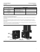
Description
The 3710 pneumatic positioner and 3720 electro‐pneumatic positioner are used with either diaphragm actuators
(spring return) or piston rotary actuators (spring return or double‐action) as shown in figure 1. These positioners
provide a valve ball or disk position for a specific input signal. These positioners can easily be configured to provide
single‐ or double‐action output for rotary actuators.
The 3710 pneumatic positioner accepts a pneumatic input signal. The 3720 electro‐pneumatic positioner accepts a
milliampere (mA), direct current (DC), input signal. Refer to table 1 for an explanation of type numbers.
The 3710 pneumatic positioner provides a valve position for a standard pneumatic input signal. The positioner may
also be split‐ranged. See table 3 for input signal ranges.
The 3720 electro‐pneumatic positioner provides a valve position for a milliampere (mA), direct current (DC), input
signal. The positioner may also be split‐ranged. See table 3.