
Instruction Manual

Instruction Manual
D200157X012
4194HS Controllers
October 2011
12
To switch from automatic to manual mode, carefully adjust the loader knob until the metal ball inside the plastic tube
moves into the switching zone. Then move the automatic/manual switch to MANUAL. Turn the loader knob clockwise
to increase the controller output or counterclockwise to decrease it.
To switch from manual to automatic mode, adjust the set point manually or with remote set point pressure to move
the ball into the switching zone. Turn the switch to AUTOMATIC and adjust the set point manually or with remote set
point pressure to control the output.
When the automatic/manual switch is in AUTOMATIC, adjusting the loader knob has no effect on the controller
output. When the automatic/manual switch is in MANUAL, changing the set point adjustment has no effect on the
controller output.
Prestartup Checks
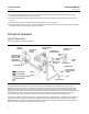
When performing the checks, open process loop conditions must exist. Refer to figure 5 for location of adjustments.
Note
If the controller has the auto/manual option (suffix letter E), be sure the controller is in the automatic mode before performing
prestartup checks.
1. Connect supply pressure to the supply pressure regulator and be sure it is delivering the proper supply pressure to
the controller. Provide a means of measuring the controller output pressure.
2. For controllers with remote set point (suffix letter M), connect regulated pressure of 0.2 to 1.0 bar (3 to 15 psig)
or 0.4 to 2.1 bar (6 to 30 psig) to the remote set point connection at the top of the controller case.
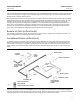
3. Loosen two screws (key 6), lift off the proportional band indicator cover (key 36), and set the proportional band
knob between DIRECT and REVERSE.
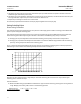
4. The process indicator should indicate the process differential pressure. For example, with the process differential
pressure at 50 percent of the input span, the process pointer should be at 50$1.0 percent of its span. Slight
adjustment of the indicator zero screw might be necessary. See figure 5 for zero adjustment and locking screw
location.
5. If desired, the accuracy can be verified at other points on the scale. If the indicator is out of calibration, refer to the
process zero‐and‐span adjustment portion of the calibration procedure.
6. Install the proportional band indicator cover (key 36) and tighten two screws (key 6).
Startup
Set the controller switching point as described in the calibration procedures.
If manual control valves are being used to bypass the control valve package (valve, actuator, positioner, controller),
slowly open the upstream and downstream manual control valves in the pipeline and close the manual bypass valve.
Calibration
Note
Some of the following procedures require that the proportional band knob be adjusted to between DIRECT and REVERSE. If this is
done, it will be necessary to set the proportional band knob to 400 (direct or reverse action) before replacing the proportional
band indicator cover.