
Instruction Manual


Instruction Manual
D200154X012
4194A, B, and C Controllers
September 2014
87
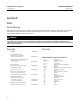
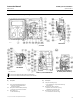
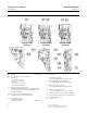
Figure 6‐1. Controller Assembly Drawings
SEE VIEW E
SECTION B‐B
38A3819‐B
56A9752‐S SHT 1
SECTION D‐D
VIEW C‐C, 4194A CONTROLLERS
CONTROLLERS WITH REMOTE
SET POINT (SUFFIX LETTER M)
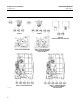
NOTE:
1 KEY 4 GASKET IS USED BETWEEN INTERNAL FRAME AND FRAME MANIFOLD.
2 KEY 5 GASKET IS USED BETWEEN FRAME MANIFOLD AND RATE/RESET MANIFOLD.
j APPLY LUB/SEALANT
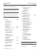
Key Description
135 Frame manifold, A03600 (aluminum)
For all types except w/suffix letter E,
auto/manual station
136 Rate/reset manifold A03600 (aluminum)
For all types except 4194C controllers
137 Rate Tubing Ass'y
4194C controllers only
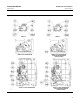
Key Description
138 Auto/manual tubing ass'y
(4)
Use w/suffix letter E, auto/manual station only
SST/aluminum
140 Machine screw, fill hd, 18‐8 SST
Required to mount remote set pt ass'y
(suffix letter M) to indicator ass'y
162 Machine screw, hex hd, 18‐8 SST
(For 4194B and C controllers only)
4. This part is included in the Auto/Manual Retrofit Kit