
Instruction Manual

Instruction Manual
D200156X012
4194HA, HB, HC Controllers
September 2014
59
Replacing the Proportional or Reset Bellows
Note
Before starting the following procedure, remove the controller from the case. Perform steps 1 through 7 of the Replacing the
Differential Pressure Unit procedure. Then, perform steps 1 and 2 of the Replacing the Case and Cover procedure.
1. Perform the procedures required in the Note above.
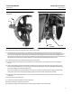
2. Remove the two screws (key 6) and lift off the proportional band indicator cover (key 36).
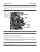
3. Disconnect link 4 (key 65) from the bellows bracket (key 31).
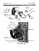
4. Remove the two machine screws (key 35, figure 5‐15) and washer (key 362) from the bellows assemblies.
5. Remove the four machine screws (key 6, figure 5‐15) from the bellows beam (key 49). Then, remove the bellows
bracket (key 31).
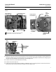
6. Remove the proportional tubing assembly (key 40) from the proportional bellows and/or remove the reset tubing
assembly (key 43) from the reset bellows, depending on which bellows are to be replaced.
7. Remove the four machine screws (key 71) from the bellows beam and remove the bellows beam from the frame
(key 3).
CAUTION
When removing and replacing the proportional or reset bellows, keep in mind the bellows has left‐hand threads.
Overtightening could damage the threads.
Note
Do not remove both bellows if only one requires replacement.
8. Unscrew the bellows (key 48). If the bellows assembly cannot be removed by hand, thread a machine screw (key 35)
into the bellows until tight; loosen the bellows assembly by applying clockwise torque to the machine screw.
9. Before installing the replacement bellows, coat the threads with a suitable lubricant, such as key 310. Screw in the
replacement bellows until it is finger tight against the frame (key 3).
10. Reinstall the bellows beam (key 49) and tighten the machine screws (key 71).
11. Compress the bellows and install the two screws (key 35) and washer (key 362) through the bellows bracket
(key 31) into the bellows. Do not tighten. The washer must be under the screw threaded into the reset bellows (see
figure 5‐15 for the location of the reset bellows).
12. Install the four machine screws (key 6) through the bellows bracket (key 31) into the bellows beam (key 49) but do
not tighten. Be sure the bellows bracket is aligned so it does not rub on the frame (key 3) at any point. Tighten the
screws (keys 6 and 35, figure 5‐15).
13. Install the proportional and/or reset tubing assembly on the bellows (key 48) base.
14. Adjust the reset valve to 0.01 minute per repeat (4194HB or 4194HC). Adjust the rate valve to OFF (4194HC). Apply
the correct supply pressure with the nozzle capped and check for leaks. Remove the supply pressure.
15. Replace link 4 (key 65) on the bellows bracket. Be sure the link does not contact the frame (key 3). If it does, loosen
the four screws (key 6) which attach the bellows bracket (key 31) and reposition the bracket to provide clearance.
Be sure the bellows bracket does not rub on the frame.